

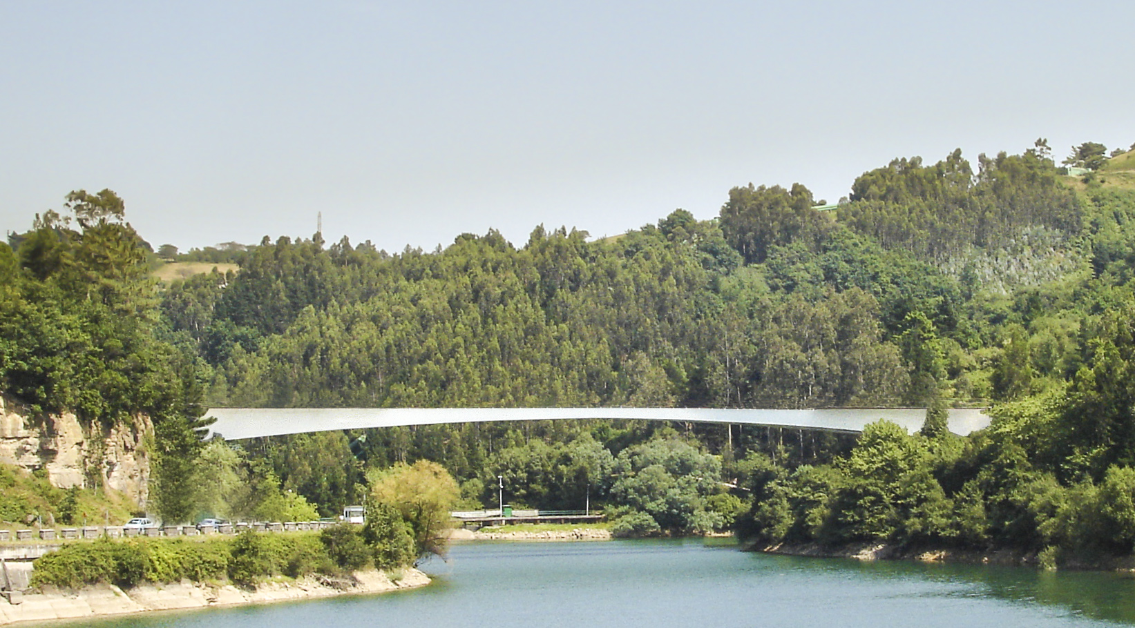
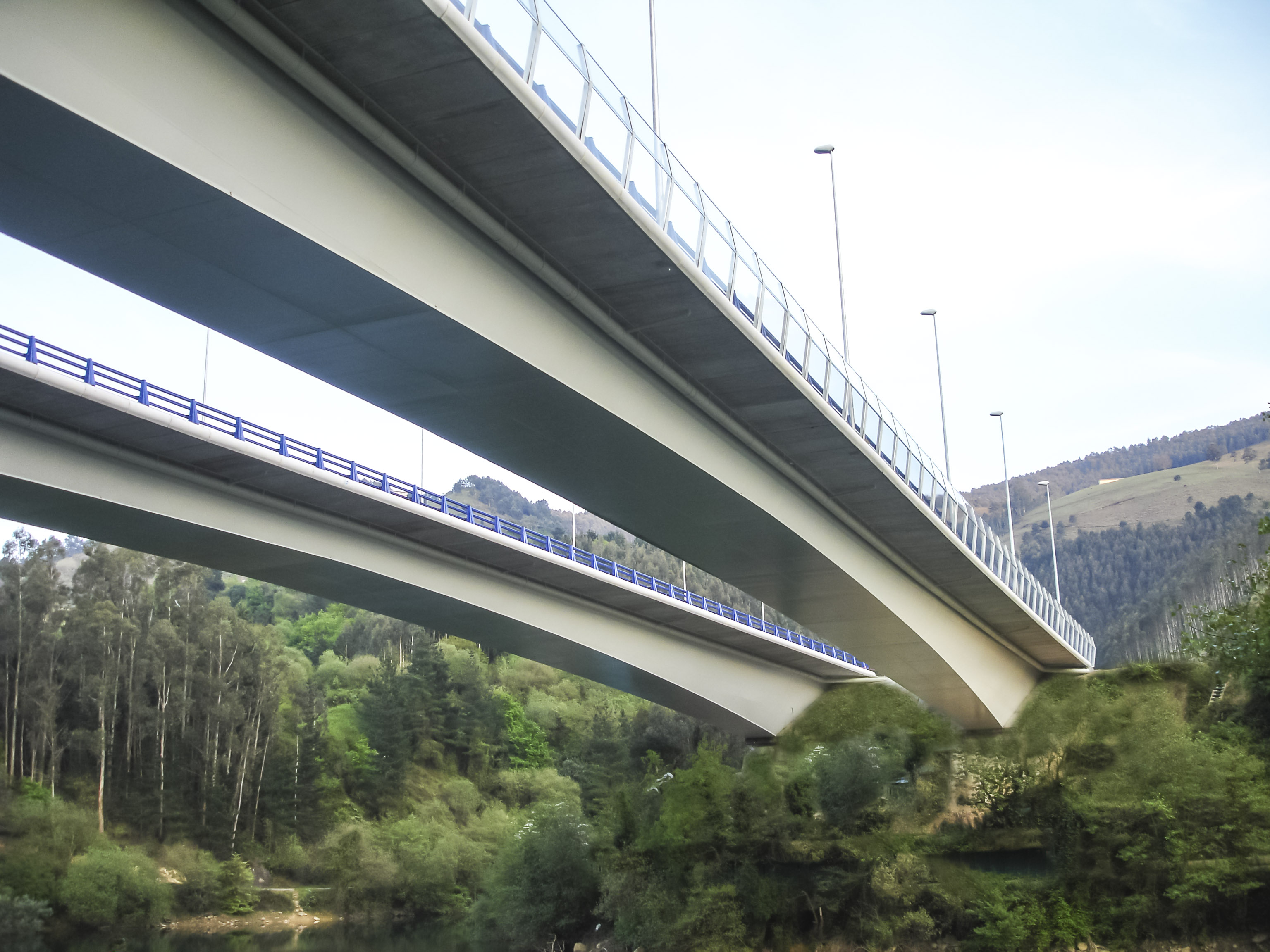
The Southern Metropolitan Bilbao Bypass crosses the Gorostiza Reservoir at a narrow stretch by way of two tunnels on either end. On the southern side two carriageways are joined together with the purpose of diminishing a steep scar that exits halfway up the slope. The bridges, one per carriageway, are enshrined in a natural setting of great beauty.
This bridge represents the fulfilment of an ambition engineers have cherished since the beginning of time: an unobstructed leap from one shore to the other with no intermediate supports.
The two bridges are almost identical. Both have a 130 m long main span with two, 30 m long compensation spans. These side spans, installed within a box allowing for their free dilation, form a counterweight for the central span and are built-in at the bridge abutments. The deck consists of three lanes, two hard shoulders and guardrails, totalling 13.60 m in width.
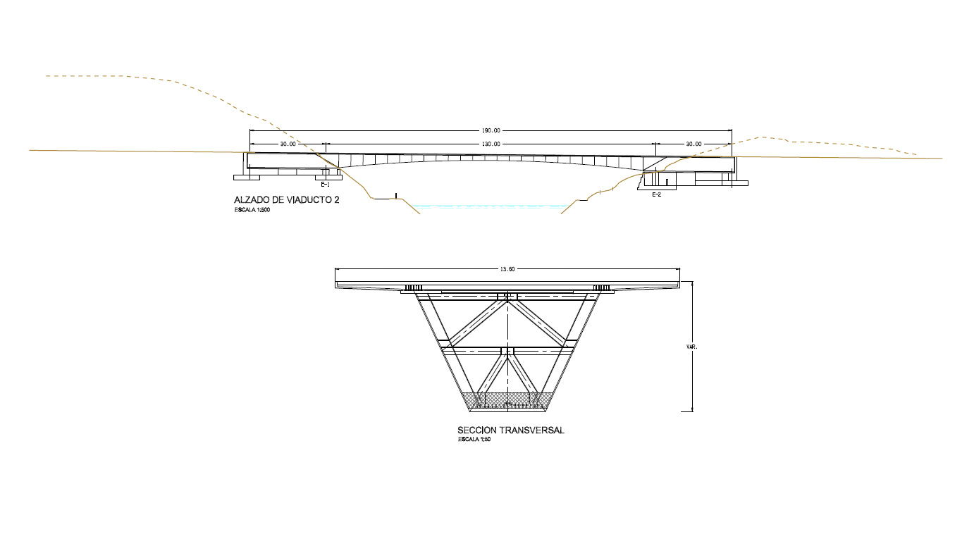
The central span is made up of a composite box girder whose depth is variable, ranging from 1.90 m at midspan to 5.30 m at the counterweights. The box has inclined webs, which leads to the variable width of the bottom plate, ranging from 2.50 m at the ends to 5.0 m in the centre. The box girder is transversely braced every four meters by means of frames and inclined struts.
The upper concrete slab thickness amounts to 35 cm, with 3 m lateral cantilevers, whose thickness is reduced to 25 cm along the edge. There is also a lower concrete slab utilised to create a double composite action. The lower slab runs from the support to 20 m away from the midspan and its thickness is variable, ranging from 40 to 80 cm.
Each abutment is built of concrete and forms a 35 m long and 13 m wide enclosure accommodating the counterweight. The height of the wall varies to adapt to the foundation level, approximately eight meters below the ground level. This is a shallow foundation that transmits all tensions below six tenths of Newtons per square millimetre to the rock.
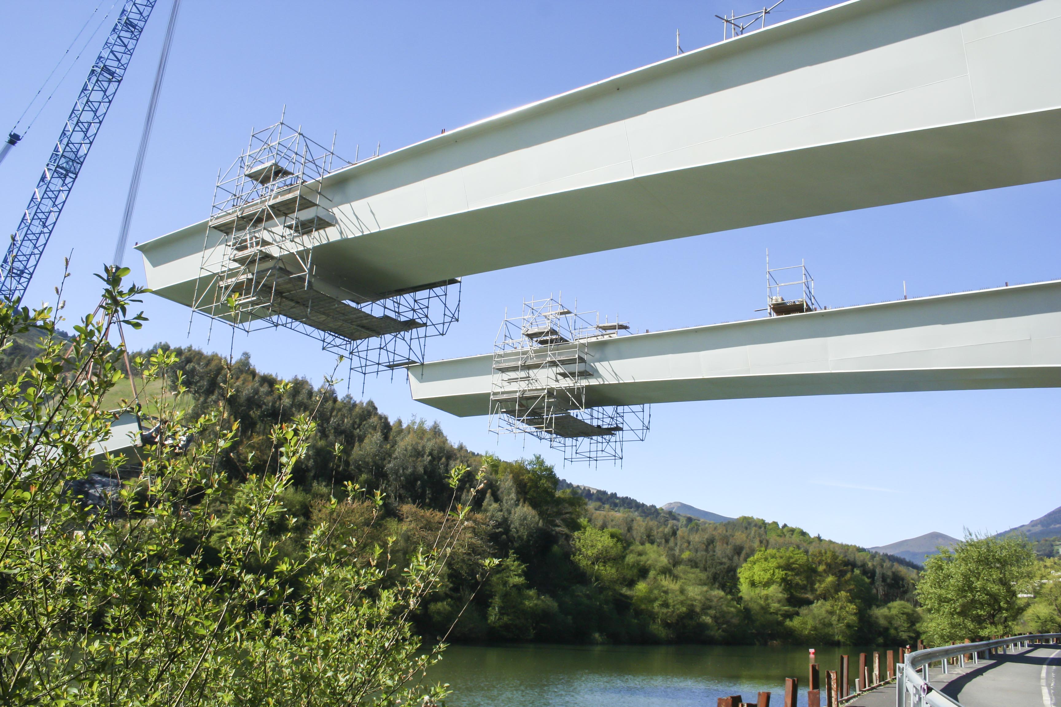
The counterweights were built on site in its position. We installed the metal box girder by hanging it from the counterweights by means of a large-capacity crane. With the aim of reducing the number of joints on the cantilever, we optimised the weight and dimensions of the segments. Their number was also reduced to four per abutment, plus the end segment.
Therefore, the bridge construction process began by placing the metal brace beam for bridge support and the plate extensions within the counterweight. After this the reinforcement was installed and concreted.
The end segment was fitted on site to the actual distance that existed between the cantilevers. For the placement of the end segments we used jacks which adjusted the edges before proceeding with the definitive welding.
Once the metal box girder was completed, the ribbed reinforced concrete preslabs were installed. The concreting was carried out in a phased manner. First the lower slab, followed by the central segment between the box girder webs of the upper slab and finally the lateral cantilevers.