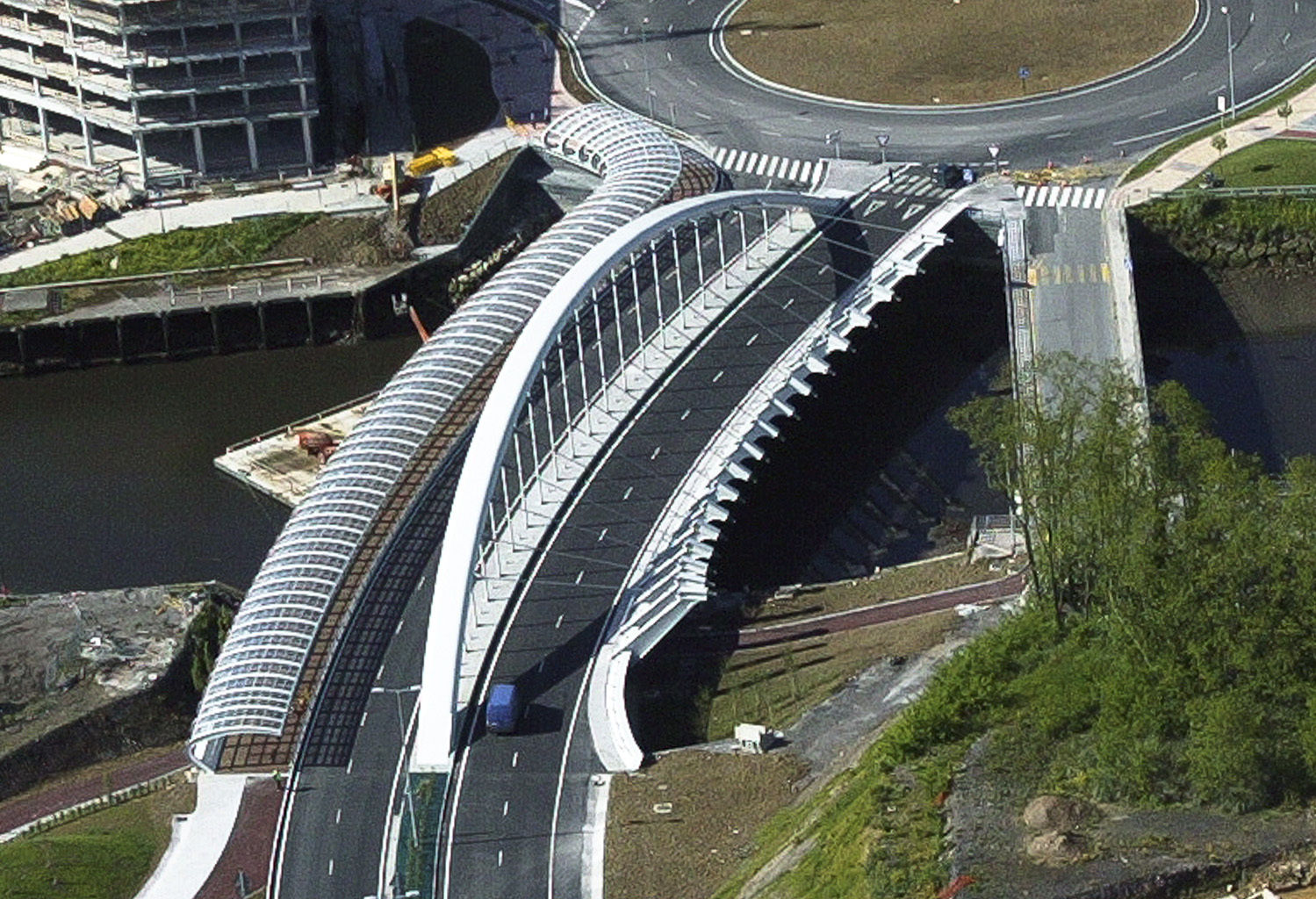
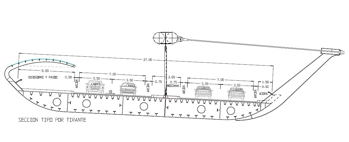
This bridge is built over the Galindo River at the river´s outlet into the Nervión Estuary. It possesses a certain obliquity and takes a clear, unobstructed leap over the river and the riverside promenades without any intermediate supports. The layout has a great curvature in the plan view with a 250 m radius, a 5% transverse grading and a 3% longitudinal slope. The bridge width is 27 m, with a median strip and pedestrian walkways on either side, a 6 m wide one along the outer edge and a mere 1.5 m wide on the inside.
View Obras CFCSL projects on a large map
Seven possible solutions were considered all of which had the structure above the deck, given the fact that the deck profile is very close to the water level. Three of these solutions had upper, lateral girders extending from the lower deck. The other four solutions were girders or upper arches placed along the median strip which had to pay heed to the fact that the median strip is not centred.
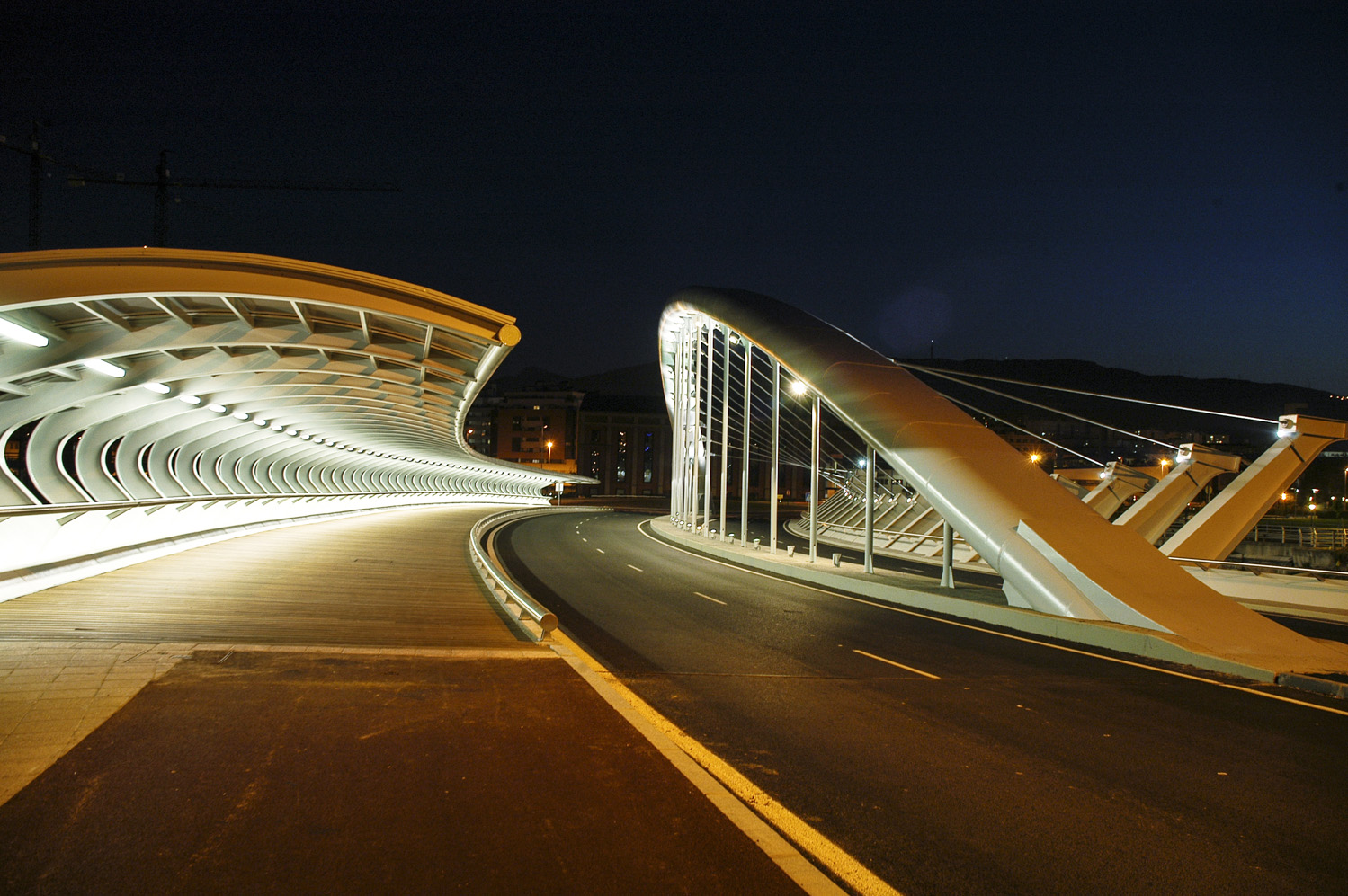
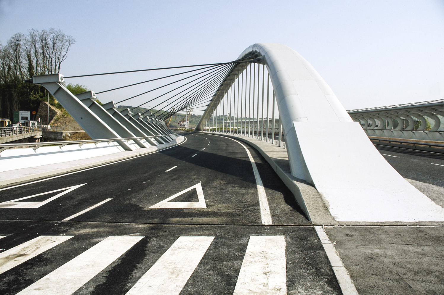
The chosen solution has a tied arch of a 110 m long span and a 16 m rise. This is the first spatial arch in the world curved in elevation and with a curved plan, in a large-scale structure. To counter the transverse horizontal loads of the arch, due to the curved plan, nearly horizontal stay cables are arranged, anchored to a series of cantilevers jutting out from the inner edge of the deck. The transverse loads are thus transformed into torsion on the lower deck.
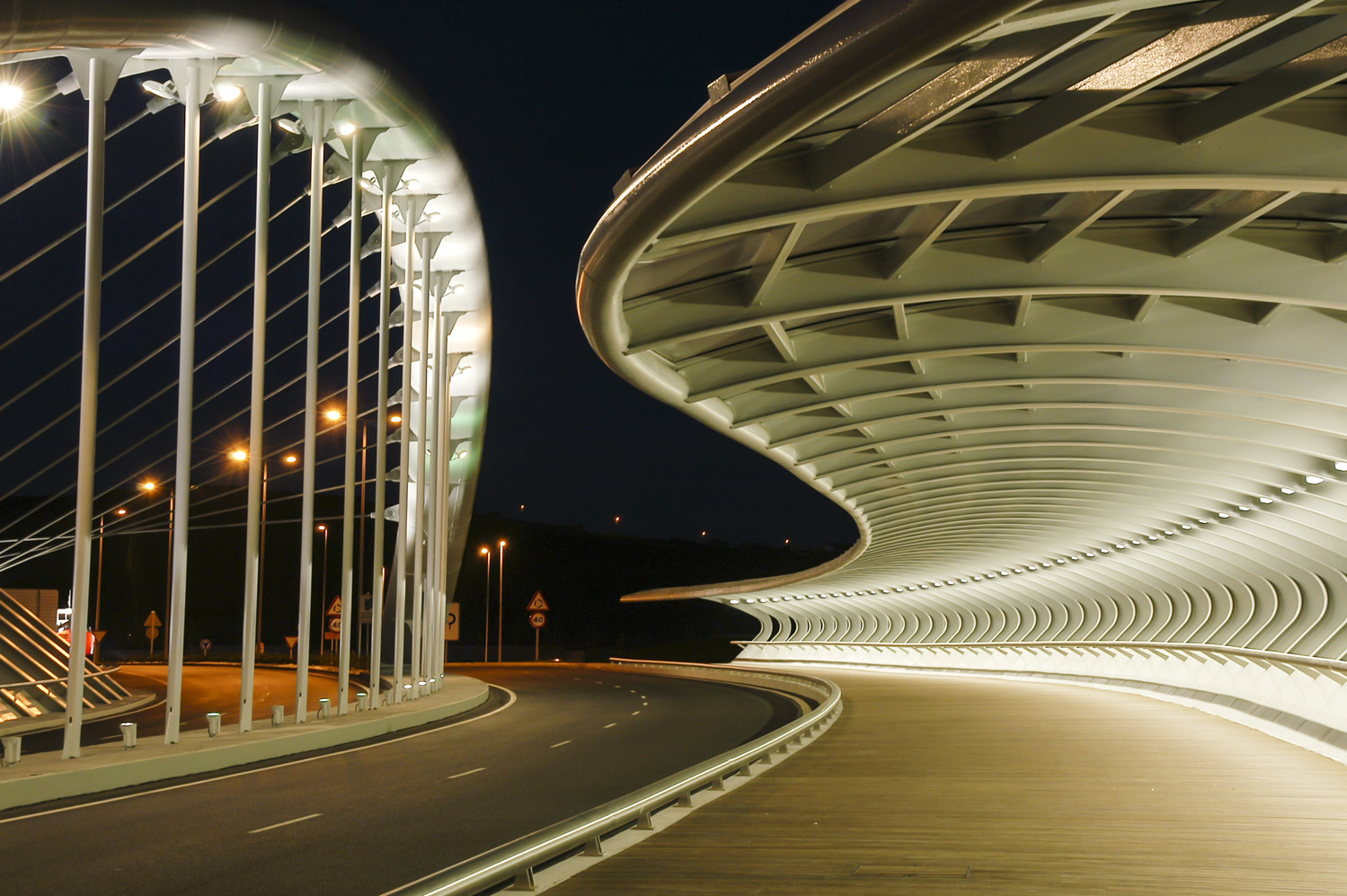
There is not a single element of the bridge that does not respond to a strict resistance demand, with the exception of the roof over the pedestrian walkway. We believe we have turned an intricate resistance problem into a beautiful and new external form.
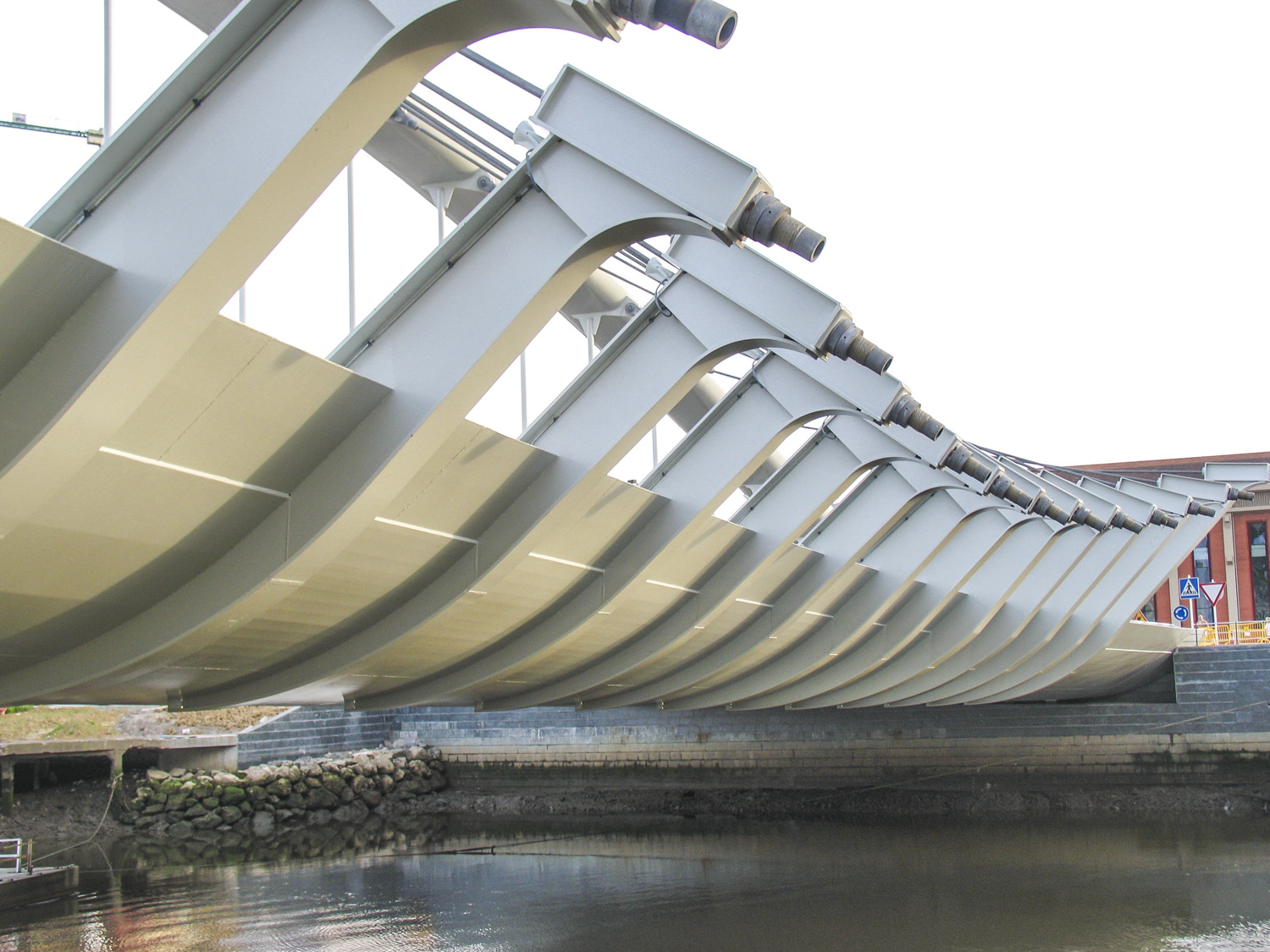
The bridge is simply supported on the two abutments. The deck has a 2 m depth and a 27.0 m width, with distinctly curved edges. The 6 m wide sidewalk is covered by a canopy roof made from steel and methacrylate. On the opposite side, cantilevered ribs jut out from the crash barrier, supporting the transverse stay cables which, in their turn, uphold the arch laterally.
The entire deck is made of steel with plate thickness values ranging from 15 to 20 to 30 mm, distributed all along its contours, depending on the resistance demands. It is stiffened both longitudinally and transversely. For transverse stiffening we arranged diaphragms every 4.4 m, whereas for longitudinal stiffening we arranged grooves to accommodate upper plates and double Ts for lower plates.
In the elevation view the arch has the shape of a 2nd degree parabola, while the plan follows the directrix of the deck. The arch is made up of two steel tubes of a 1.219 mm diameter and a 50.8 mm thickness, linked at the upper and lower ends by way of horizontal, 50 mm thick plates.
The connection of the arch and the deck at their built-in union is carried out using 4 longitudinal plates, two per arch, whose thickness values are 80 mm and 90 mm respectively.
The connection of the arch, the transverse stays and the vertical hangers is carried out by means of transverse, 30 mm thick plates. These cut through the arch and are linked on the one end with the vertical hangers and on the other with the active transverse stay cables. The hangers are made of circular 193.7 x 19 mm tubes, while the stay cables are made of closed-coil cables of a 83 mm diameter. The connection between the arch elements and these transverse plates must be performed assuring full weld penetration. The arches stretches between the vertical plates are straight, which greatly simplifies the execution.
The construction was carried out by way of four provisional supports with the provisional piles of their foundations within the river. The deck cross section was divided into 22 m long and 5 m wide parts that were gradually mounted on the abutments and provisional supports with the help of cranes. The part of the deck already welded was used to proceed with the next parts.
The arch was also mounted on four provisional towers in the same vertical plane as the supports in the river. The parts were installed using cranes and were then welded to the part installed previously.
The loading of the quasi-horizontal stay cables was performed gradually in three stages from the ends towards the centre. When the operation was almost completed the provisional supports were dismantled. The vertical hangers were gradually loaded by deformation, upon the removal of the provisional piers and loading of the active stay cables.
The foundations of the L-shaped abutments are made up of 14 piles of a 1.5 m diameter, with a rectangular footing of a 6.6 m width, 2.5 m thickness and 29.8 m length. The abutment 1 also has a circular wall of a 3 m radius with shallow foundations, separated from the abutment itself. Furthermore, both abutments have one slab that serves as a transition to the embankment.
An 8.9 m cantilevered canopy is installed along the outer concave edge of the deck, supporting a transparent roof made of smooth methacrylate.