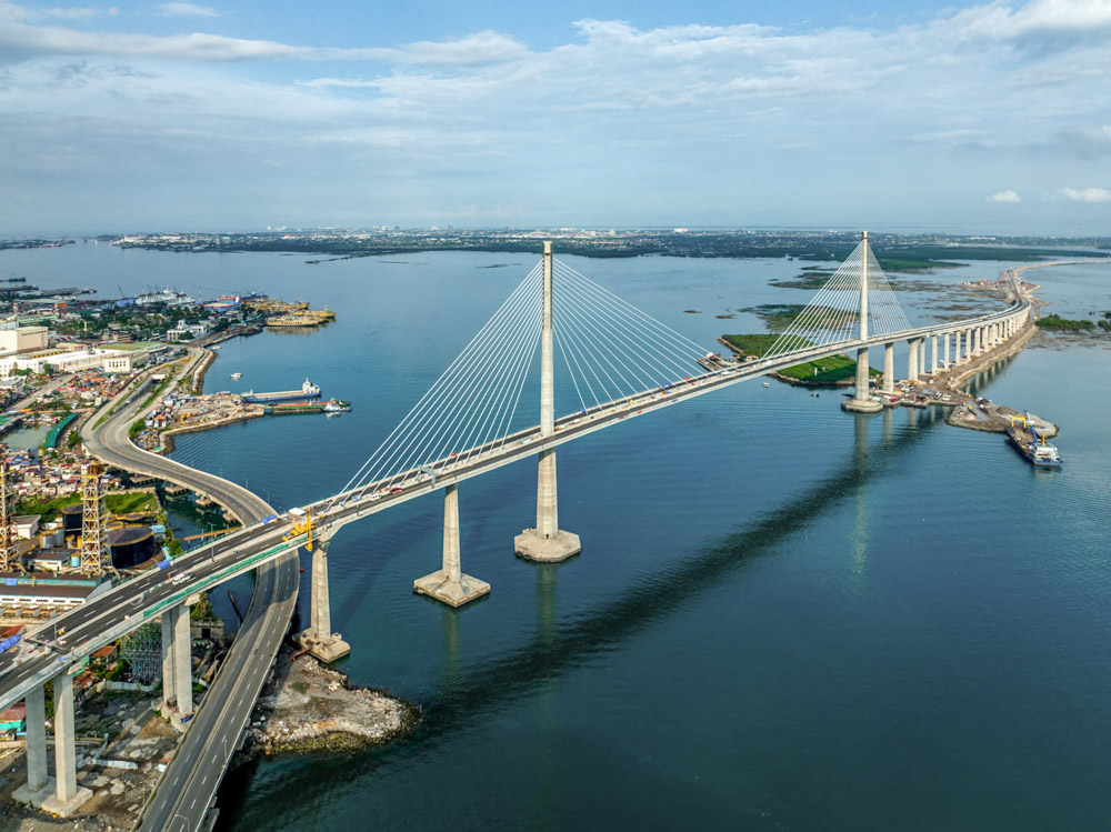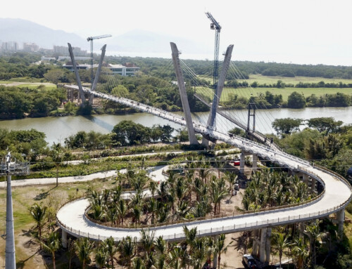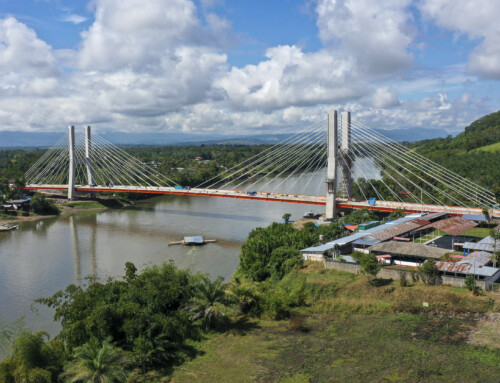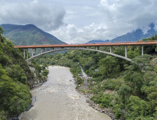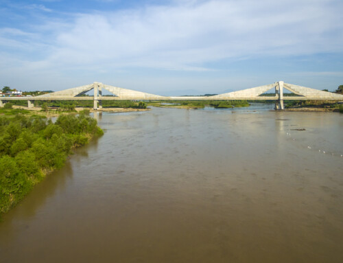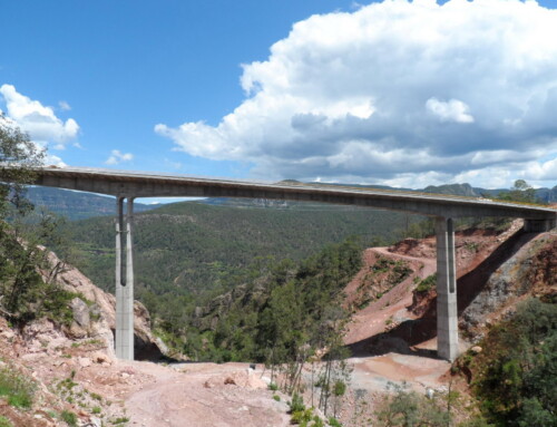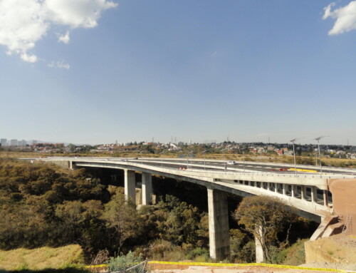
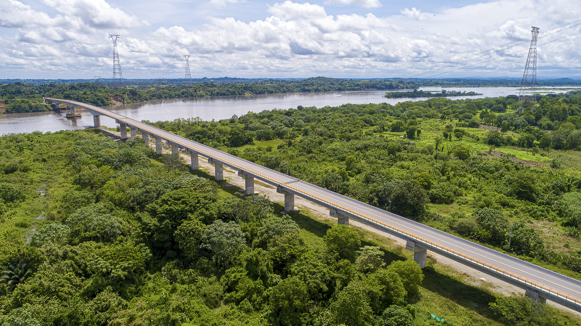
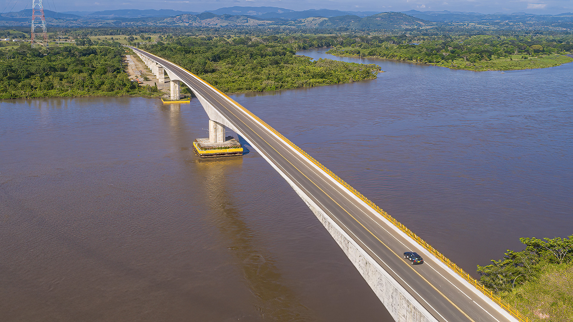

Bridge over the Magdalena River in Puerto Berrío. Colombia. 2020.
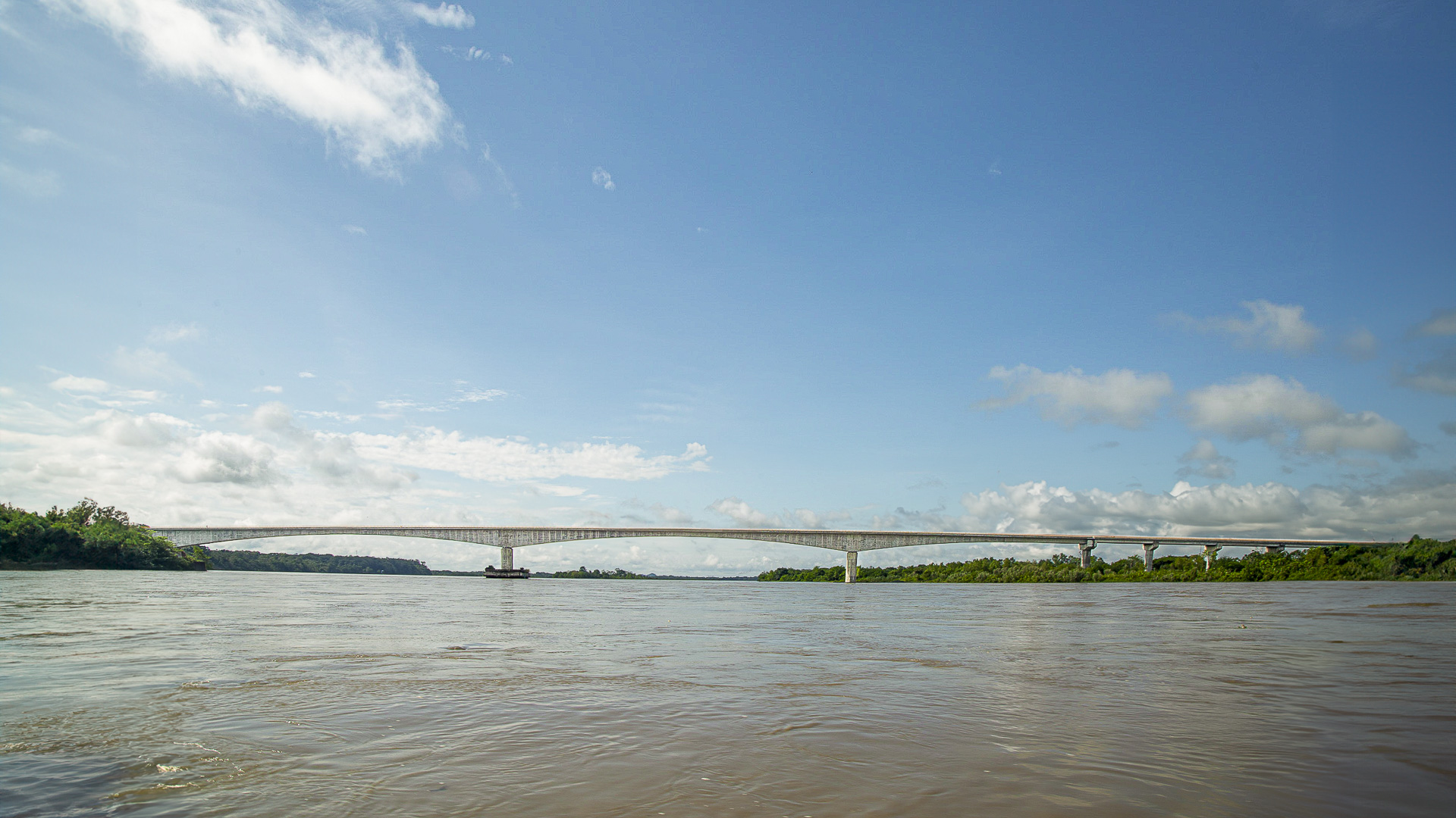
The bridge project over the Magdalena River consists of the construction of a road bridge with a total length of 1,360 meters. The distribution of spans is 17 x 40.0 m + 140.0 m +2 x 200.0 m + 140.0 m.
This is a concession signed by the National Infrastructure Agency (ANI), initially awarded to OHL and whose construction has been completed by Aleática.
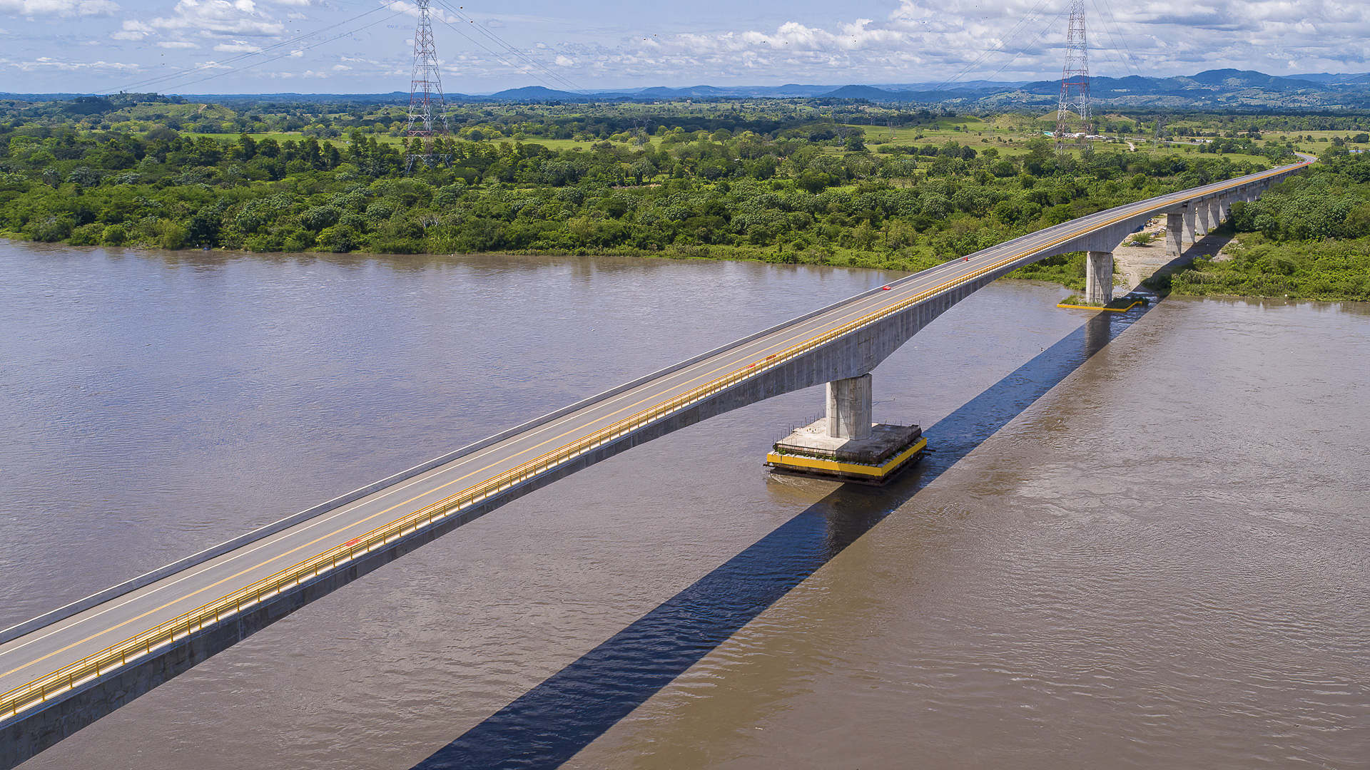
The main section originally consisted of a portico with a span of 200 m and offset spans of 100 m, with V-shaped piers embedded in the deck.
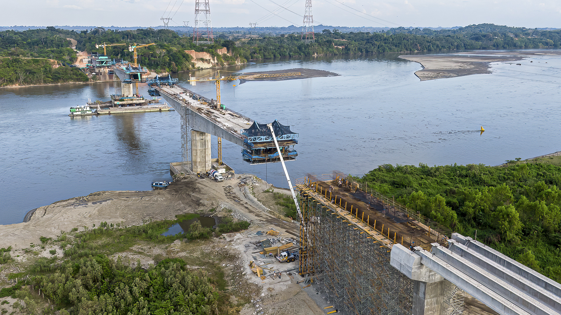
During the construction of the foundations, the scour expected in 100 years occurred, which made the construction of the foundations that were not already finished unfeasible, and made it necessary to modify the distribution of spans and thus the configuration against horizontal loads, with lead core seismic isolators.
OHL entrusted CFC (Carlos Fernández Casado S.L.) with the technical support to propose a solution to this problem.
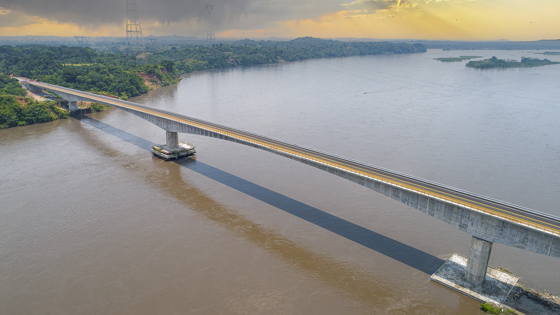
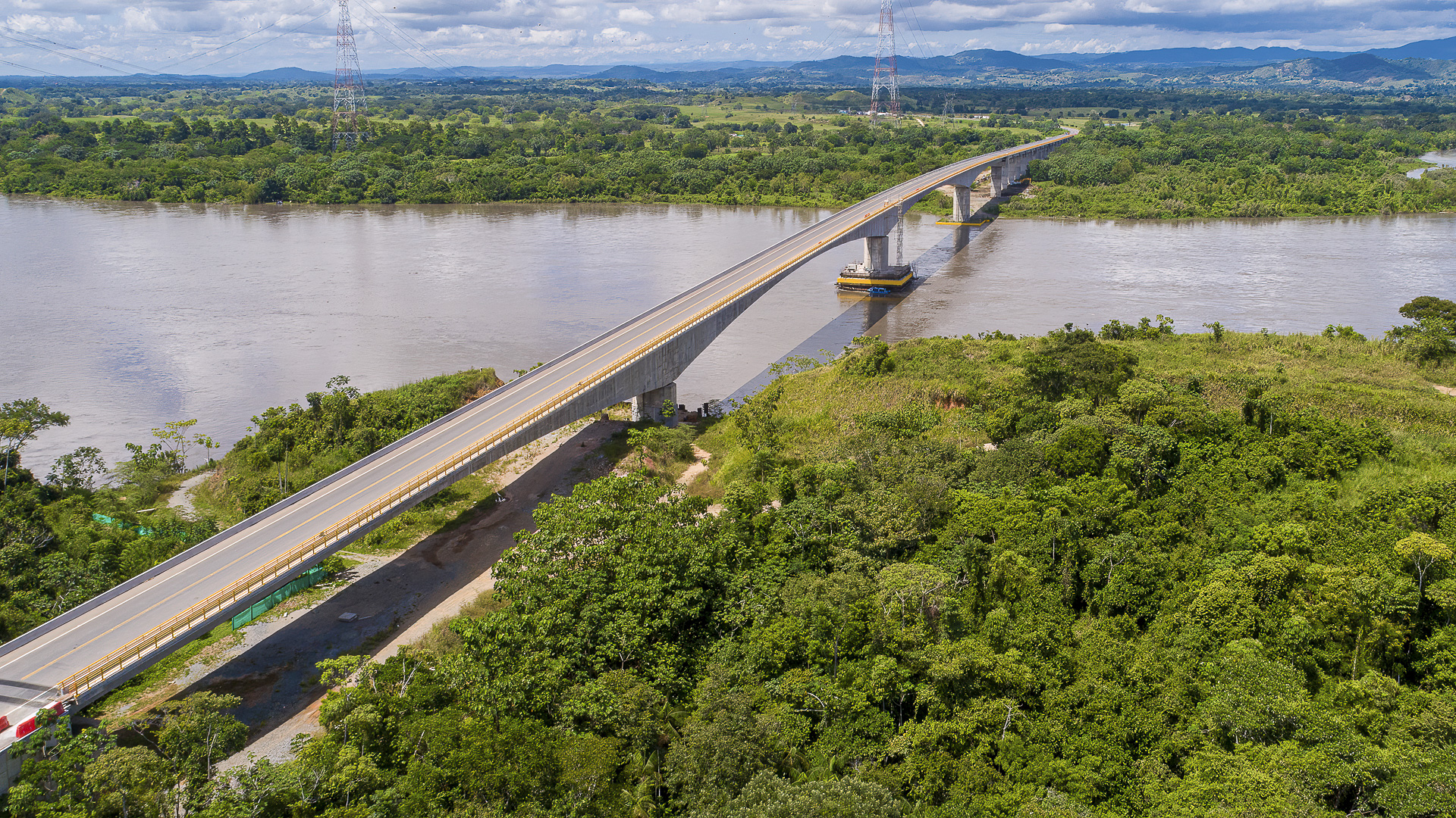
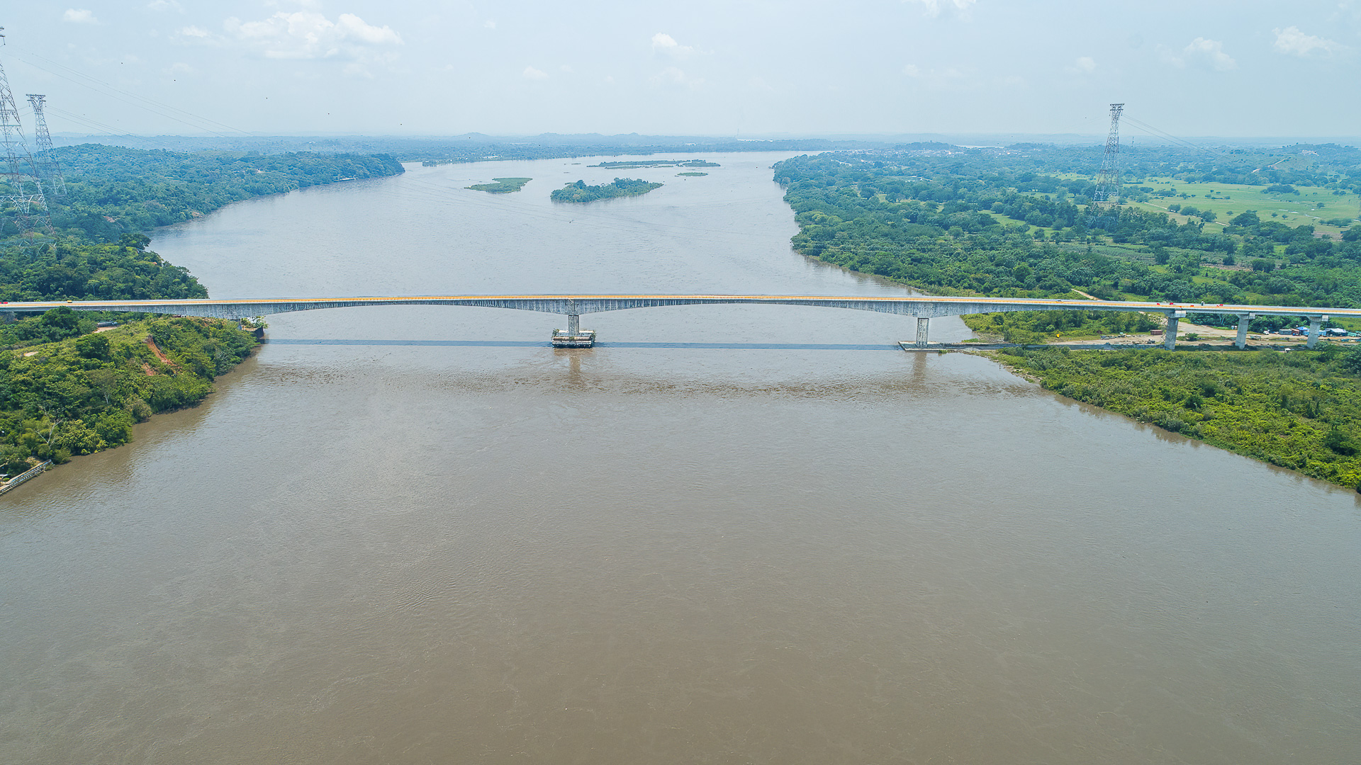
After evaluating various alternatives, the conclusion reached was that it was advisable to double the 200 m span by extending the new span towards the right bank to save the area where the initial project had foreseen the implementation of piles in the water.
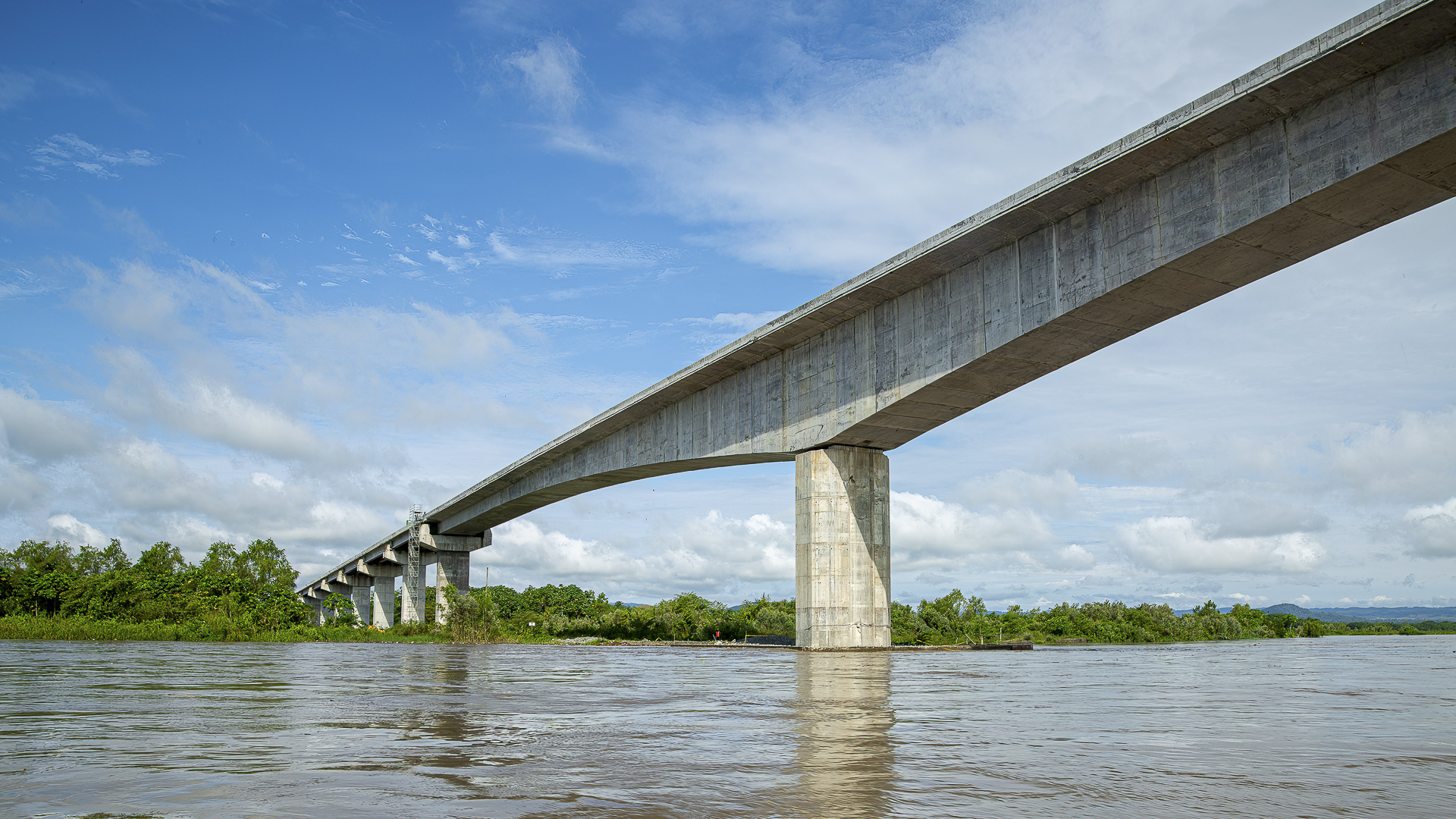
The configuration foreseen in the original design with V-shaped portal frames for the 200 m main span proved to be unsuitable for the four-span bridge, since the reduced height of the piers provided excessive stiffness of the system against longitudinal movements caused by temperature and rheological effects, which produced a level of reactions incompatible with the foundations already built.
For this reason, the design of these piles was changed to vertical elements with a single support in which an isolation and damping solution using LRB was used to optimize seismic behavior.
In parallel, it was proposed to adjust the compensation spans by extending them to be greater than half of the central span, a favorable configuration for prestressing and to avoid uplift reactions in the end piers. This led to the fact that P18 of the initial project was not necessary.
Once the solution was approved by the authorities, CFC developed the corresponding modified project for OHL and provided technical support for the construction.