

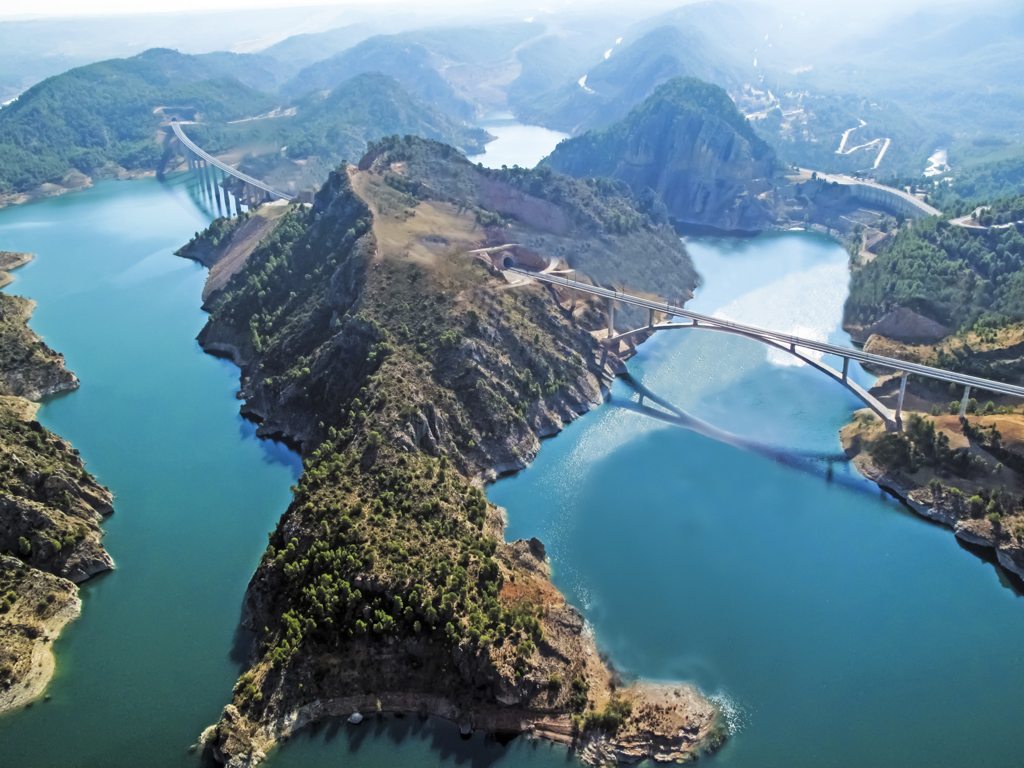
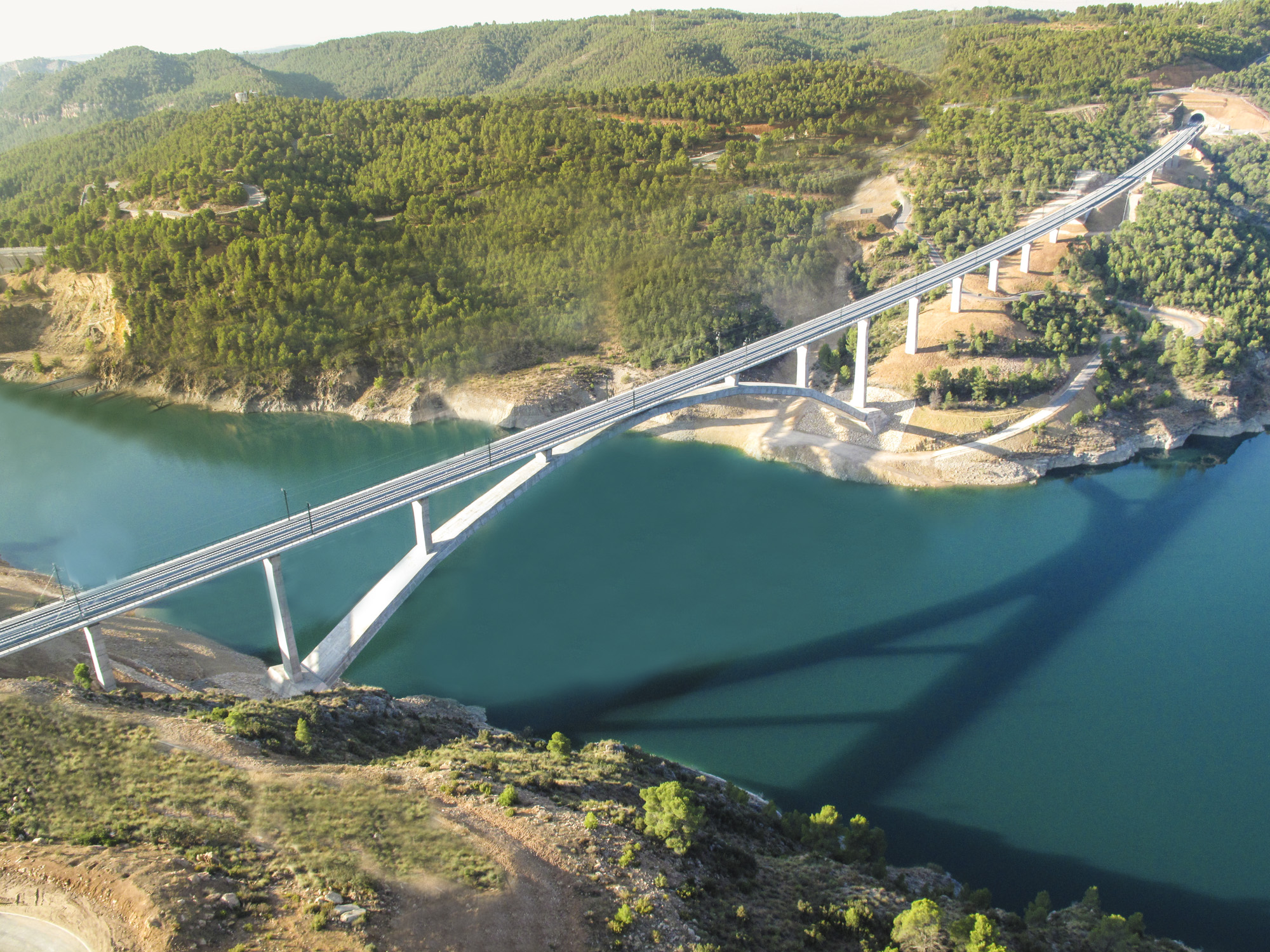
The High-Speed Railway Line Madrid-Castilla La Mancha-Comunidad Valenciana-Región de Murcia with its 914 km length of is one of the longest in Spain and it is also among those passing through the largest number of provinces. On the stretch between the Contreras Reservoir and Villagordo del Cabriel there are a series of tunnels and four viaducts, two of which cross the Contreras Reservoir, namely the Isthmus Viaduct and the Contreras Viaduct itself.
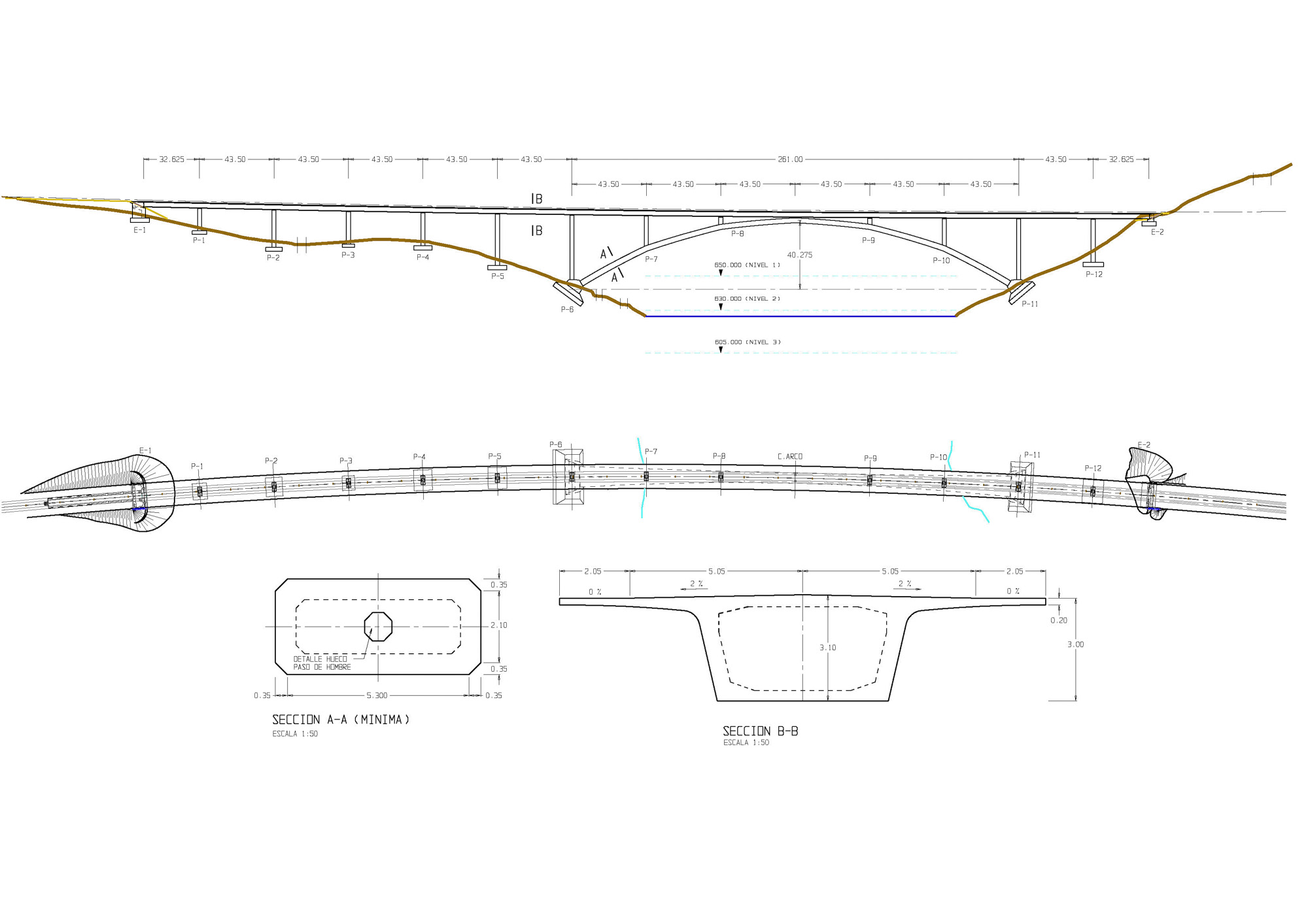
The 261 m span arch was divided in six parts by the deck columns and we opted for a polygonal directrix. The line of thrust of the arch is thus perfectly preserved, while reducing the bending moments that would exist in the area between the vertical columns if the arch were perfectly curved. The design is therefore as rigorous and minimal as possible.
The bridge is located between the km points 210+429.375 and 211+016.625 and its overall length amounts to 587.25 m. This is a reinforced concrete arch bridge with an upper prestressed concrete deck and two approach viaducts. The arch span measures 261 m and the mid-span sag is 36.944 m, which determines a span-to-rise ratio of 1/6.77 thus resulting in a low-rise arch, albeit not excessively low. It should be noted that the span between the arch supports makes the Contreras Reservoir viaduct the world´s longest among the concrete railway arch bridges to date.
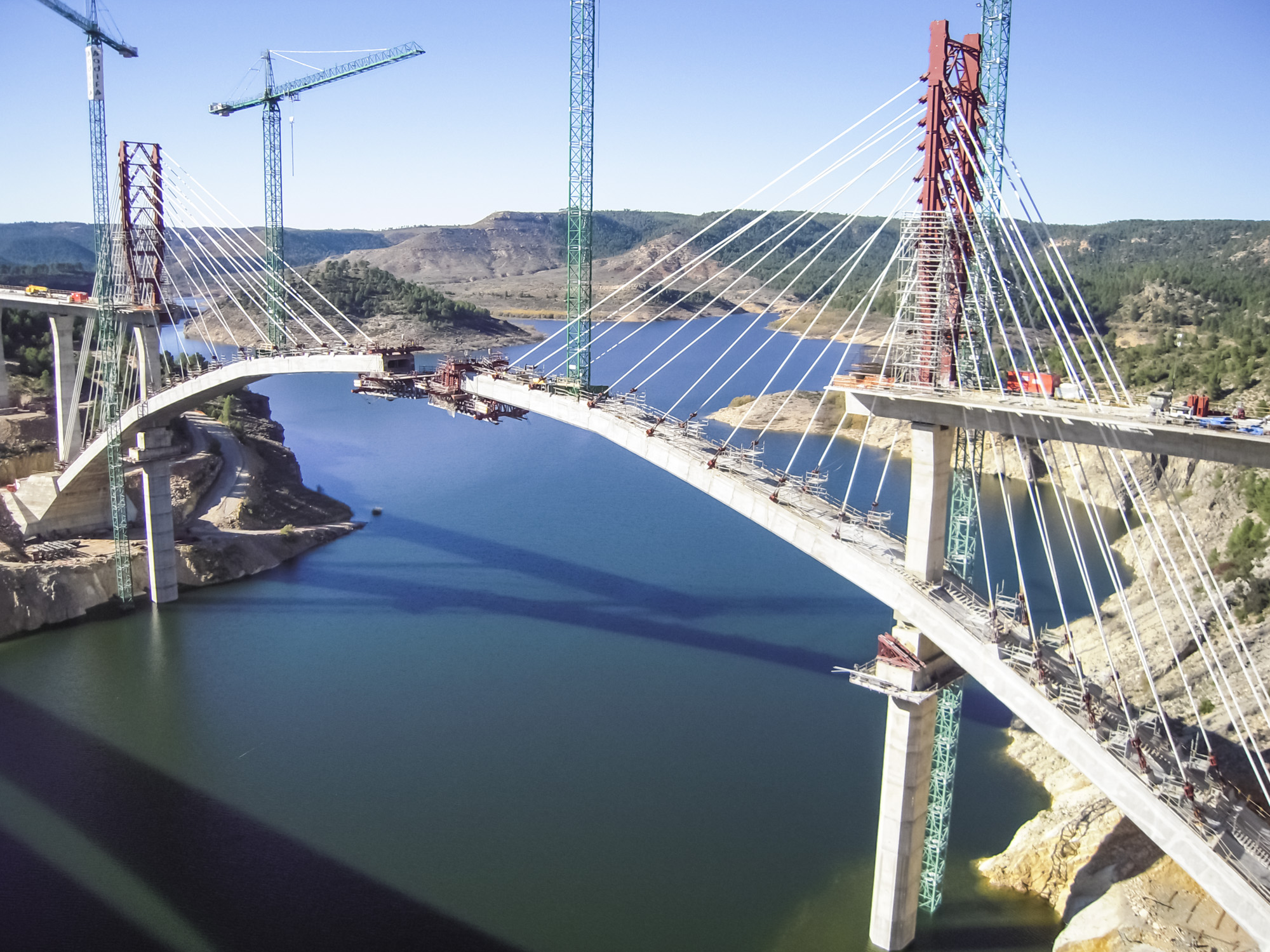
The arch is built-in at two large plinths that allow the diffusion of the load over the affected ground by means of direct foundations.
The cross section is a box girder with a variable depth ranging from 2.8 m at mid-span to 3.4 m at the ends. The box girder width is also variable ranging from 6.0 m in the centre of the arch to 12.0 at the foundations embedding, which is the width required to resist the great bending moments of the vertical axis produced by the plan curvature of the arch and the crosswind. The box girder walls range from 0.6 to 1.35 m
The upper deck span distribution is 32.625+12×43.50+32.625 m. The piers P-6 to P-11 are supported on the lower arch structure.
The layout of the viaduct area is made of two circular plan alignments with the respective radii of 4000 and 3500 m and a transition curve with a parameter of 1973.44 m. In the elevation view, the layout is situated in a parabolic transition with Kv of 25,000 m. In this project we first intended to build a deck using the incremental launching procedure which is why the viaduct axis was designed within a circular alignment of a 3875 m radius, which caused maximum eccentric forces between the rail axis and the deck of 0.11 m. For this reason the platform was widened to 14.20 m. The sliding axis in the elevation was also a straight alignment, which produced drops of 1.7 m with regard to the theoretical alignment. These effects, of both the eccentric forces and drops were taken into consideration when the deck was designed.
The deck is made up of a 3.00 m deep box girder -which determines a span-to-rise ratio 1/14.5-, a 5 m wide lower slab and a 6.50 m wide upper one, and a series of segments that complete the total section width of 14.20 m. The web thickness is 0.50 m. The webs are thickened over the piers until reaching a total thickness of 1.27 m to allow the anchoring of the service prestressing cables.
The lower slab is 0.30 m thick. The arch has a polygonal curved directrix in the vertical plane, which corresponds to the non-funicular of the permanent loads. In the plan view the arch is drawn within the circular alignment of 3,875 m radius in order to avoid eccentric forces at the points where the piers are built-in with the arch. It is made of reinforced concrete with the strength of fck=70 MPa, due to the great compressive forces it must endure.
The variable height of the piers ranges from 3.53 to 35.38 m. All the piers are composed of one basic pier with a rectangular box-girder cross section of a 2.60 m constant width and a variable depth ranging from 5.20 m on the upper edge, 3.20 m at the “waist” situated 5 m away from the upper edge, and a widening towards the base.