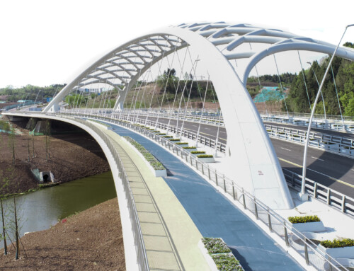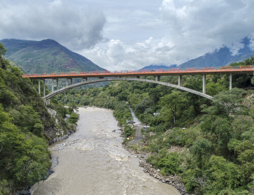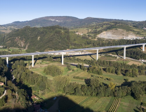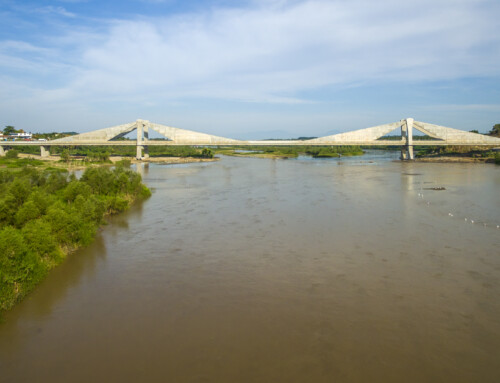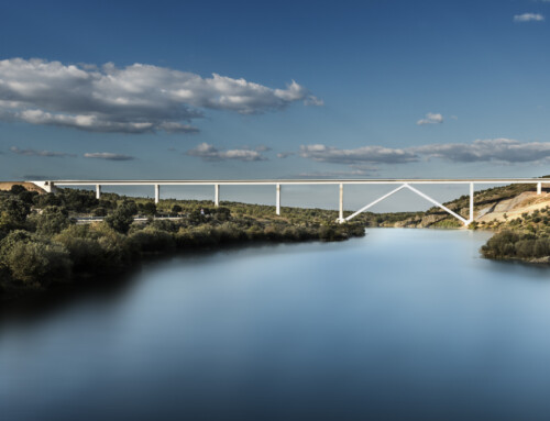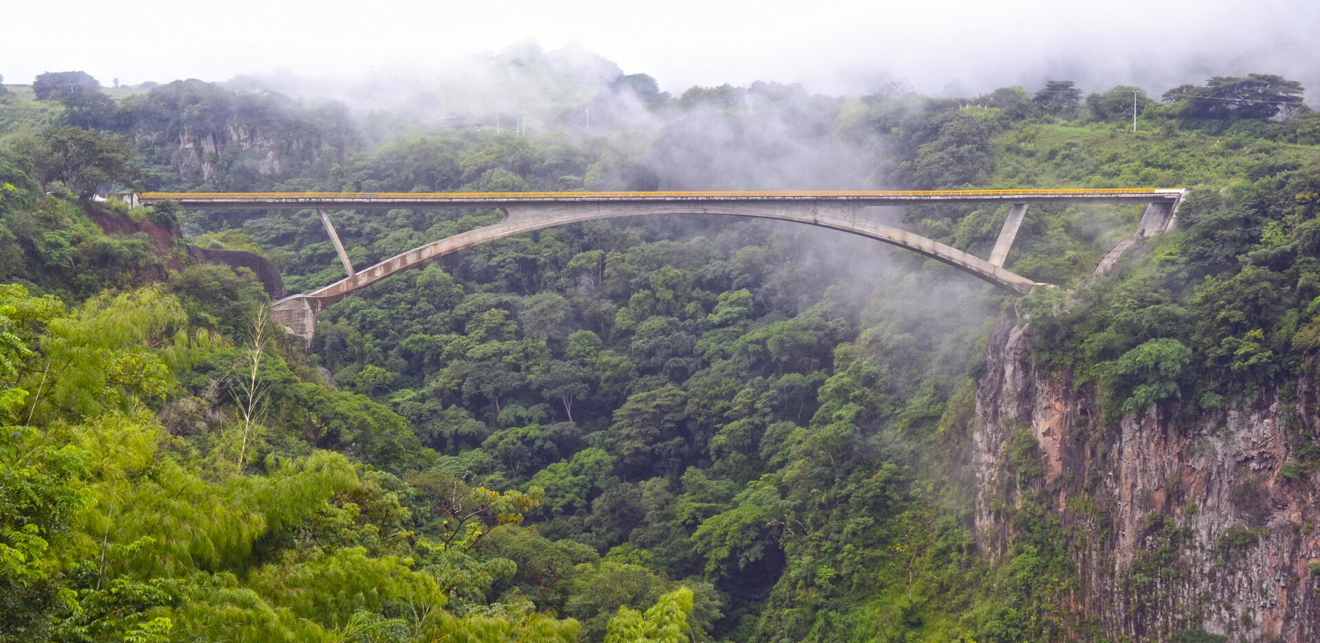
San Sebastian Bridge Jalisco. México. 2009
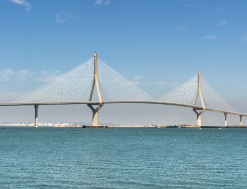
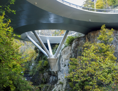
The San Sebastian Bridge spans over a gorge formed by its river namesake in the Mexican State of Jalisco. The project was carried out in collaboration with the Mexican company Mexpresa (Mexicana de Preesfuerzo), our regular partner on all our Mexican projects. The two main problems we faced on this project were due to the steep slopes of the ravine and the high seismicity of the region. The morphology of the ravine admitted only one logical bridge solution, namely that of an arch spanning from one edge of the gorge to the other. The gorge dimensions deliver a 135 m span arch. The inaccessibility of the slopes -virtually vertical in the upper section- only allowed access to the arch foundations from the top edges of the ravine. Consequently, we designed an arch with the lowest possible rise/span ratio, thus making the access path to the foundations from the top edge as short as possible. In fact, given the verticality of the slopes, the excavation of the foundations had to be initiated starting at the ravine´s upper fringes. Unfortunately, the excavation of the foundations was not executed with all due meticulousness, which produced a deterioration in the appearance of the area surrounding the foundations. The intense seismicity of the region also affected the project. It made us install shock transmission units on either end of the deck in order to avoid transverse stresses on the bridge. The common method applied to withstand earthquake effects usually consists of using shock absorbers that allow large movements of the structure in order to minimise the internal forces produced by the earthquake. This notwithstanding, we have also come across certain cases, such as the present one, in which we were forced to install devices that are able to allow movements produced by slow deformations (temperature, shrinkage, creep), while at the same restraining the movements produced by quick deformations (earthquakes), as will be shown later on.
Description of the project
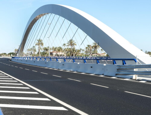
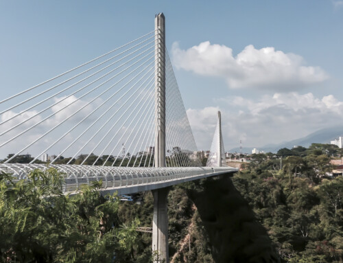
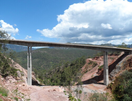
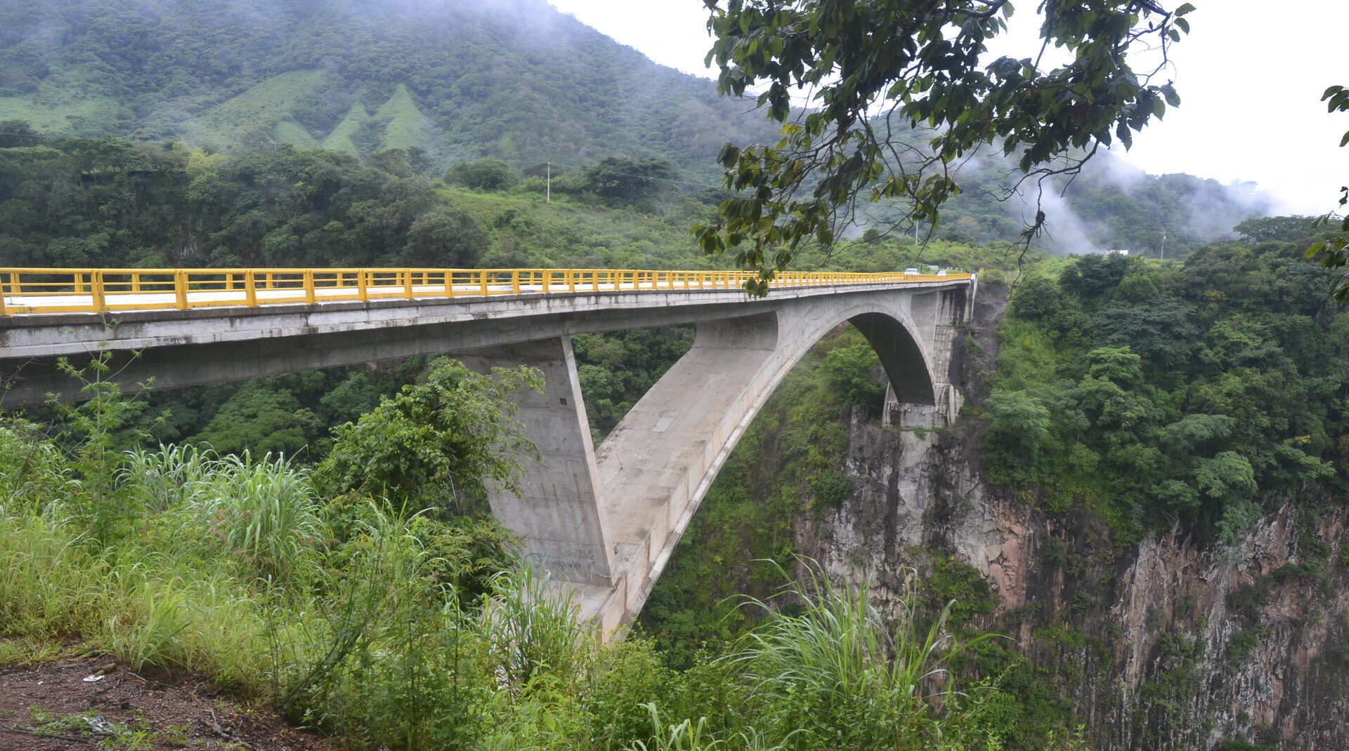
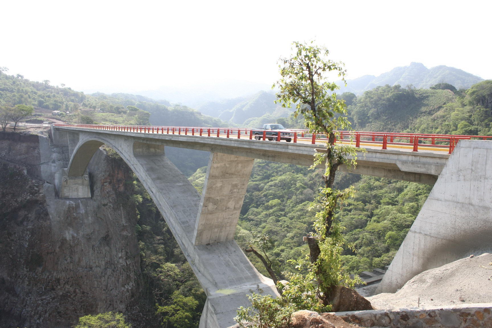
As mentioned above, we sought to design an arch with the lowest possible rise/span ratio (1/15 of the span) in order to achieve the smallest height from the deck to the foundations. To this end we not only had to obtain a low rise arch, but also design the arch and deck of a similar depth at midspan. These two elements are built-in together in the arch´s central stretch, whose length in this case amounts to 50% of the arch span. Therefore, the need for matching arch and deck and their bifurcation made us design a deck with a depth resembling that of the arch albeit somewhat smaller: the arch depth amounts to 2.50 m (1/55 of the span), while the deck depth amounts to 1.40 m + 0.20 m along the sidewalks. As a result 30 m spans (1/20 of the span) were designed. The deck length from the arch-deck intersection area to the abutments amounts to 60 m on either side. These spans were then divided into two 30 m long ones by way of built-in inclined piers between the arch and the deck. The total length of the bridge between the abutments amounts to 193 m. Both the deck and the arch are 6 m wide single-cell box girders. The deck box girder is laterally extended through 2.25 m cantilevers in order to reach the total carriageway width of 10.50 m.
Project problems
The bridge is formed of a fixed arch built-in with the deck on the central stretch. The deck extends on either side through continuous girders whose ends rest on the abutments; this is hence a simple structure which does not pose any particular problems except those that may arise in case of earthquake. The earthquake produced effects may be divided into longitudinal and transverse ones. In this case there appear no longitudinal problems because the structure withstands these effects perfectly well without any noteworthy increase of the forces. The problem arises in the transverse structure. The deck was initially envisaged as supported on the abutments with free longitudinal displacement and transverse restraint, meaning that the deck was free to twist in the vertical axis, in other words, allowing free twisting in its plane. Under these conditions the longitudinal deformations of the deck caused a displacement at the top of the inclined diaphragms. This displacement produced intense bending moments here, but most of all, introduced twisting moments that the arch was unable to resist, which posed an unsolvable problem. The only solution under such conditions implied a significant increase of the width and depth of the structure. Without changing the bridge dimensions we could only reduce the transverse deformations of the deck. To this end, we were to restrain the twisting in the plane on either end, which would have required the constraint of the longitudinal displacements. This constraint is impossible since the displacements due to temperature, shrinkage and creep should not be constrained in the ends of a bridge which is 193 m long. For this reason we had to install shock transmission units that allow slow movements (temperature, shrinkage and creep) while blocking the quick ones (earthquake, braking). Therefore, in case of earthquake the deck is built-in its vertical axis on either end. The rest of the issues in this project did not pose any particular problems. The deck is prestressed in its entire length and the foundations are supported in a solid rock, which required several connections by means of prestressed anchors, basically due to the geometry of the ravine slopes.