

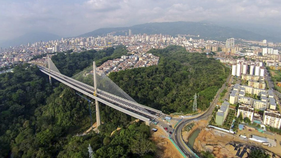
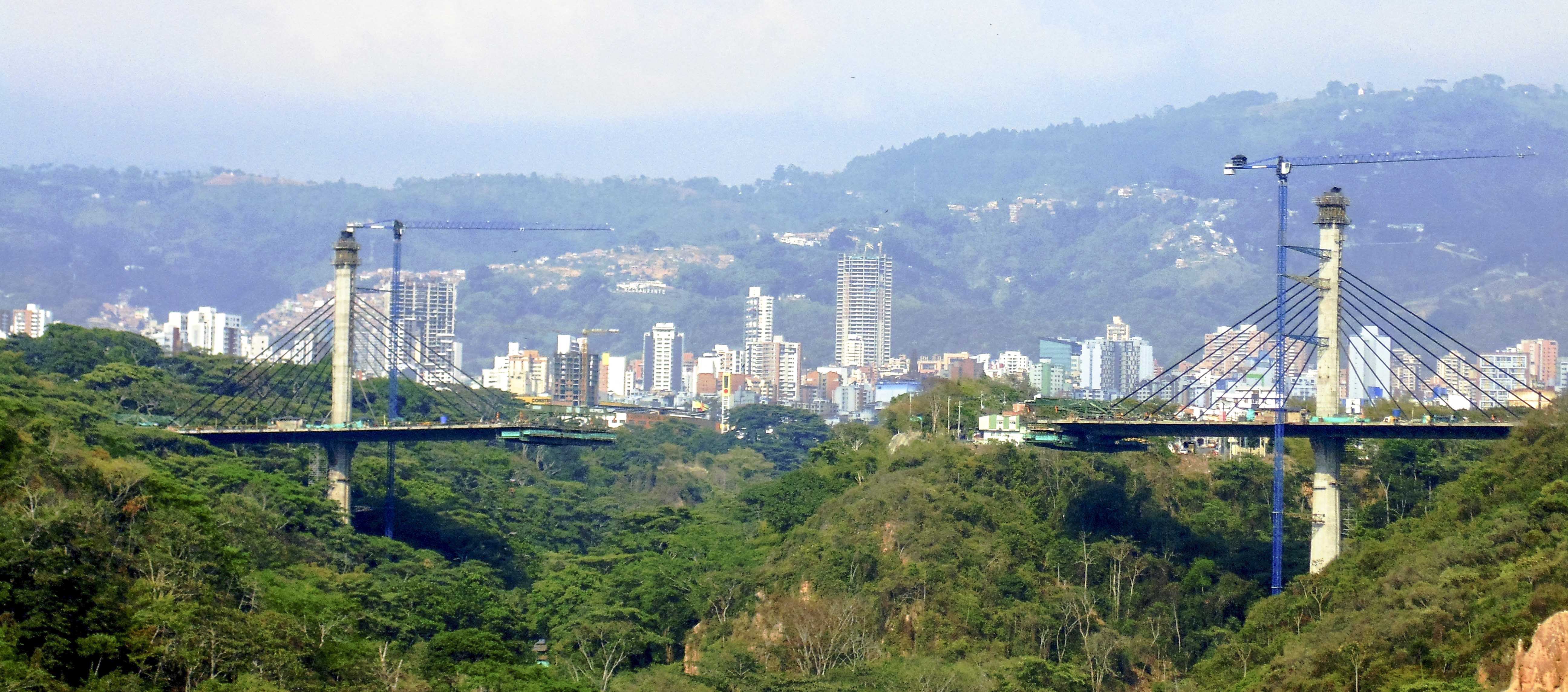
The purpose of the Carrera Novena Viaduct in the city of Bucaramanga is to span the ravines of Rosita and Loro thus bestowing continuity on the city interrupted by the gorge.
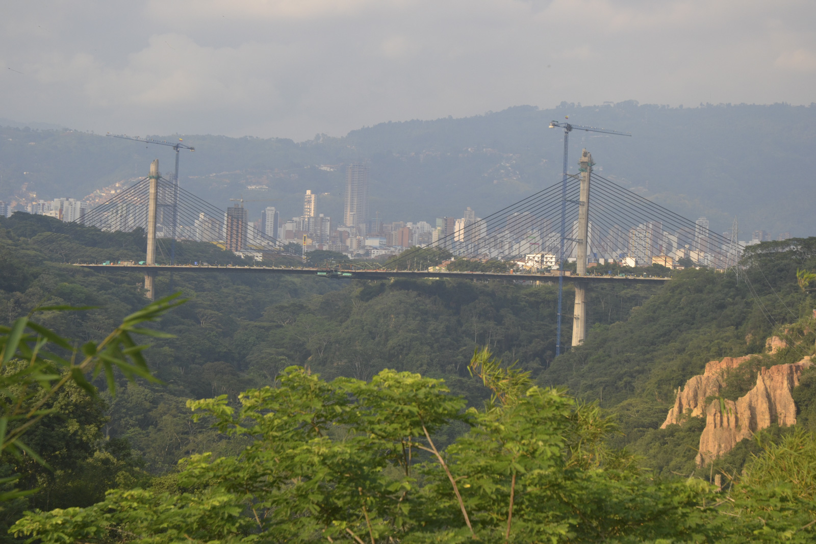
The Carrera Novena Avenue passes close to the confluence of the two ravines. This is why the crossing was solved by building a single viaduct of a 550 m long span, equaling the distance between the outer edges of the ravines. Maximum conservation is required for the densely wooded slopes inside the gorge possessing a great environmental value. Therefore, we proposed a viaduct with large span lengths that would narrow down the number of the piers embedded in the ravines to as few as possible. Given the viaduct length, a three-span solution was applied: the central span amounts to 292.4 m, while the side ones are 129.2 m long.
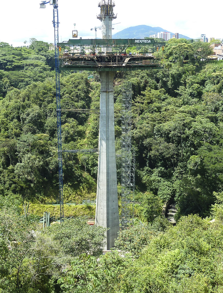
The three spans call for two piers which are placed in the area with the flattest surface configuration close to the ravine floors. As a result of such flat configuration we needed to move the least amount of earth to build the foundations. This circumstance led to pier heights of 52 m and 72 m respectively, measuring from the foundations to the deck level.
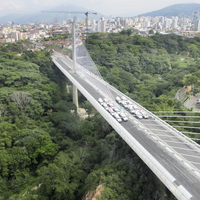
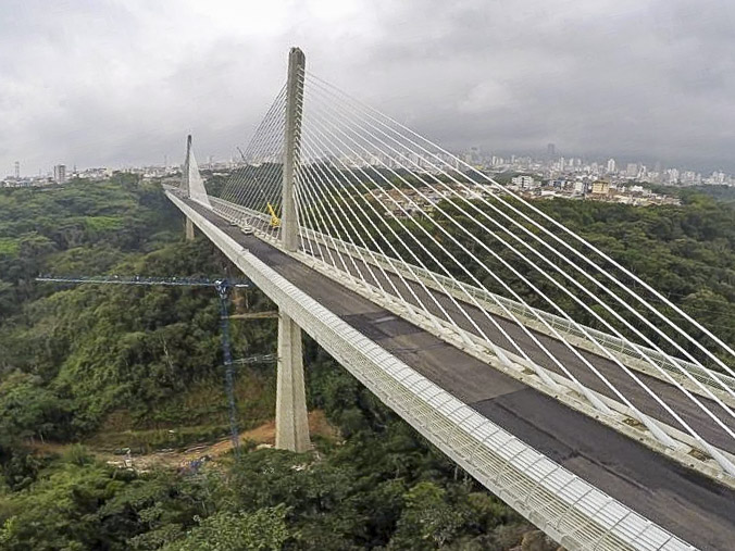
The Carrera Novena is to become a large six-lane avenue with two-meter wide pedestrian walkways along either edge. In addition, enough space must be left for the barriers as well as the stay anchors. The result is a deck with a total width of 30 m, which is an exceptionally wide deck for this type of viaduct.
The central span, reaching almost 300 m in length, requires a long span bridge, which led us to adopt a cable-stayed solution. The deck was cable-stayed along its axis using a single set of stay cables, which allowed us to better solve the question of continuity between the pier below the deck and the tower above. This was done using the same continuous structure consisting of a single shaft that runs from the foundations to the tower top. The total height of piers plus towers amounts to 113 + 133 m.
A key issue arising from the structure of this viaduct is its seismic resistance due to the fact that earthquakes may reach great magnitudes in this region, thus conditioning even the type of the structure chosen. Following the design of the deck and the towers, we carried out a number of studies of different types of structures, varying the conditions of the connection between the elements and weighing whether or not to use dampers. The solution deemed most suited and therefore also the most economical was to build rigid joints at the pier-deck-tower intersections, which produced a frame elongated by the compensation spans, supported on the abutments.
Once this structure was defined there was a possibility to install longitudinal dampers in order to reduce the effect of the earthquake, but the difference between installing dampers and installing sliding bearings at the abutments proved to be small. The only advantage of the dampers was that they slightly reduced longitudinal movements. However, the slight difference in movement plus the saving achieved by avoiding dampers led us to allow free longitudinal movement in the abutments while coercing the transverse movements in these as well as in the piers. This configuration produces a force couple of on the abutments causing a vertical pull on one of them and increasing the vertical push on the other. This situation may be symmetrical like any other earthquake effect.
The viaduct has deep foundations with piles of 1.50 m in diameter and 18 m long. The strong bending moments in the piles due to the horizontal seismic forces required pile caps of 25.5 x 25.5 m, with 36 piles in each. Since the difference in height of the two piers is compensated by their mutual difference in flexibility, the foundations of both piers have the same configuration and dimensions.
The most singular feature of the bridge is the deck due to its 30 m width and the fact that it is cable-stayed along its axis. The deck is built from a single-cell trapezoidal box girder of a 2.80 depth, with an 8 m lower edge and 11 m upper one, basically determined by the transverse bending of the deck as well as the torsion due to asymmetrical loads produced by the cable staying along the deck axis.
These dimensions produce the need for 9.50 m lateral cantilevers and a 9 long span slab between the box girder webs. This means that the section must be triangulated using lateral struts and interior diagonals set every 3.40 m. The stay anchors are placed every 6.80 m, which is to say every two triangulations. The behaviour of the interior diagonals will therefore be different in the sections with stay cables and those without.