

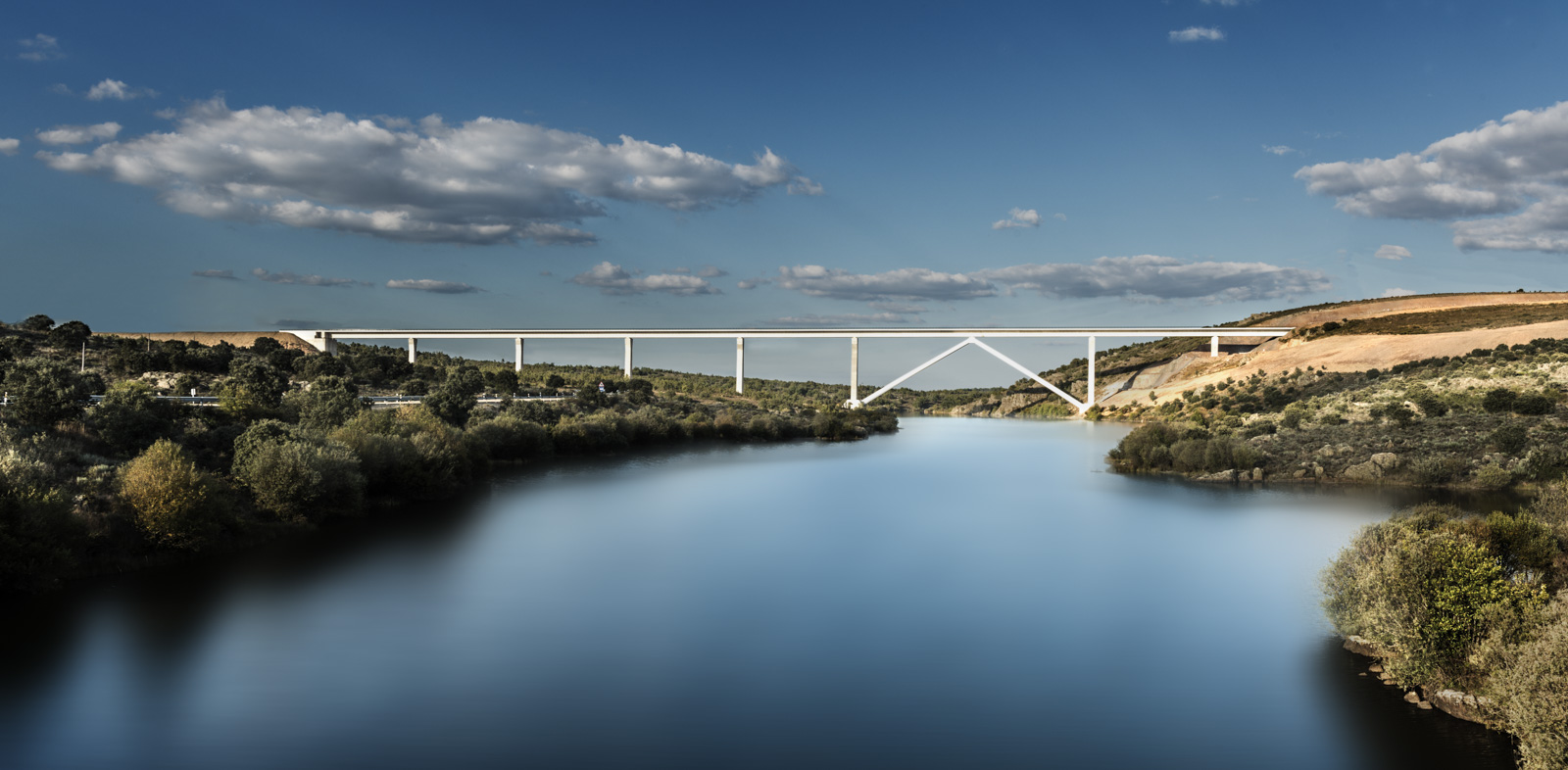
The Tera Viaduct is situated over the river Tera River between km points 710+697.500 and 711+342.500 of the north-northeast corridor of the Madrid-Galicia high-speed railway line.
It is therefore 645 m long with a span distribution of 60-75-150-75×5-60. Such arrangement, with one large 150 m span, is dictated by the crossing of the Tera River, at a point where piers cannot be built within the riverbed due to the presence of a relatively deep lagoon.
The solution we gave to the deck in terms of construction and resistance requirements consisted of obtaining a longitudinally continuous platform, modulated in a repetitive manner. This was done with the aim of applying the same type of resistant cross section in the entire structure, namely that of a constant depth box girder, as well as the same construction process, namely the incremental launching, along the entire length regardless of the relative position within the work. In this way, while adopting the typical span modulation of 75 m in the approach spans, we built an arch divided in two halves which spans the 150 m river span supporting the deck at midspan. The deck span is therefore divided into the abovementioned 75 m. We thus solved the construction problem and at the same time obtained an aesthetically attractive outcome.
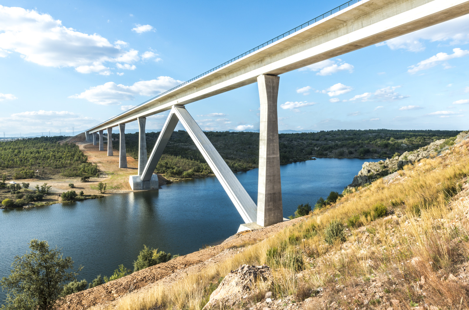
The deck dimensions and proportions are those typical for railway bridges built by incremental launching: the 14 m wide platform is placed on a box section, constant depth girder, made of prestressed concrete, with a constant 4.40 m depth and 5.20 m width and inclined, 0.5 m thick webs.
There are no tension problems in any of the pier supports. At the abutments, however, the supports are placed slightly wider apart in order to avoid these problems, therefore requiring a transverse beam which is installed in both abutments in a second stage.
The deck sits on concrete piers with a hollow rectangular cross section, -except at the head-, whose longitudinal dimension is a constant 3.50 m, while the transverse one is variable, with a 1/40 slope running from a neck placed below the pier head and whose minimum dimension amounts to 3.20 m. The upper head is bell-shaped, 5.20 m wide, decreasing lineally until reaching the neck area at the height of 7.5 m.
The same as in any other incrementally launched bridge, two groups of prestressing cables are arranged. The straight cables provide due compressions for the launching stages, while the undulating cable groups, which are loaded once the launching has concluded, provide the additional capacity to resist the increased service loads.
All the supports of the bridge are sphere-shaped, with one free unit and another transversely guided one in each pier at Abutment 1. At Abutment 2 both units are free.
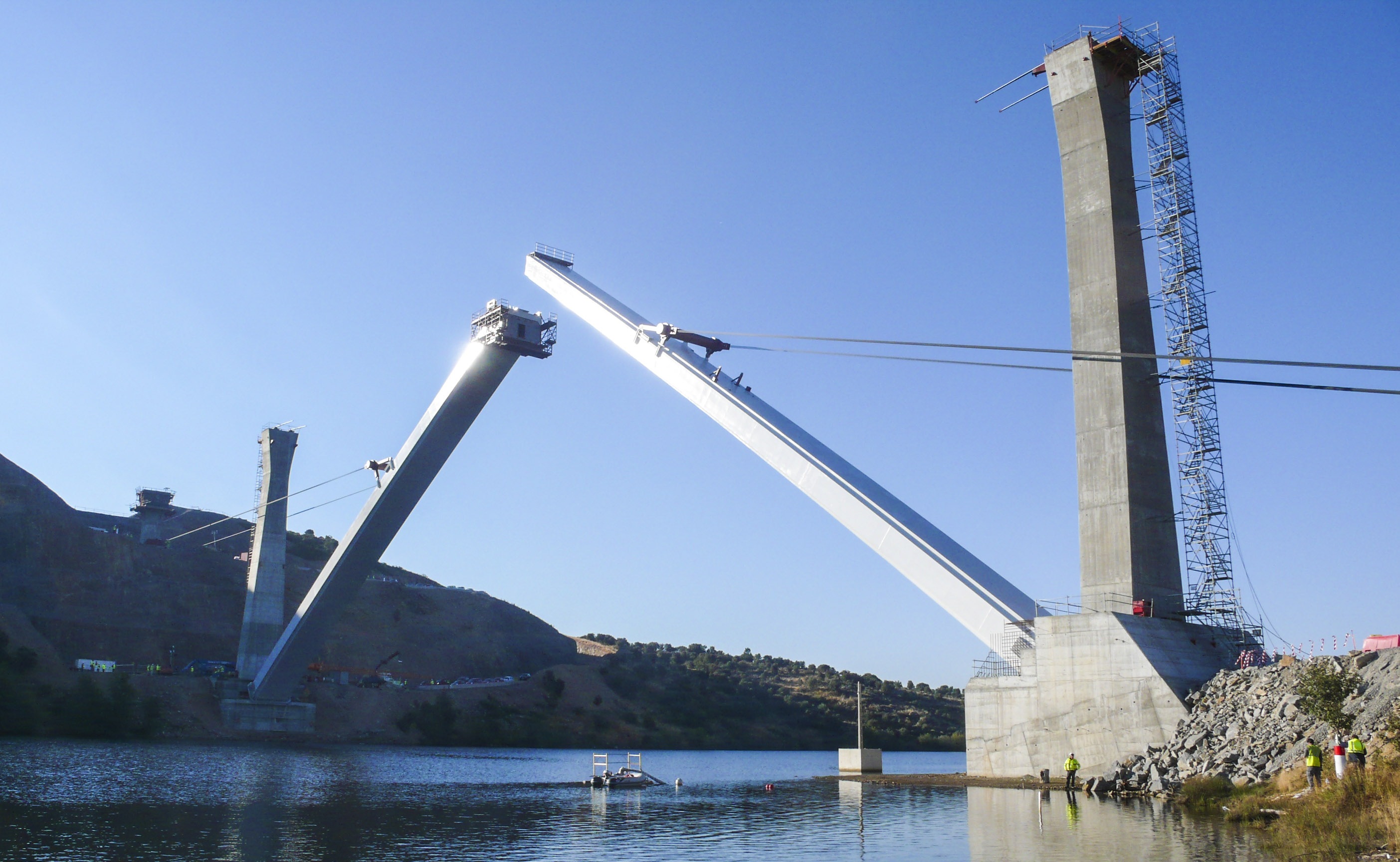
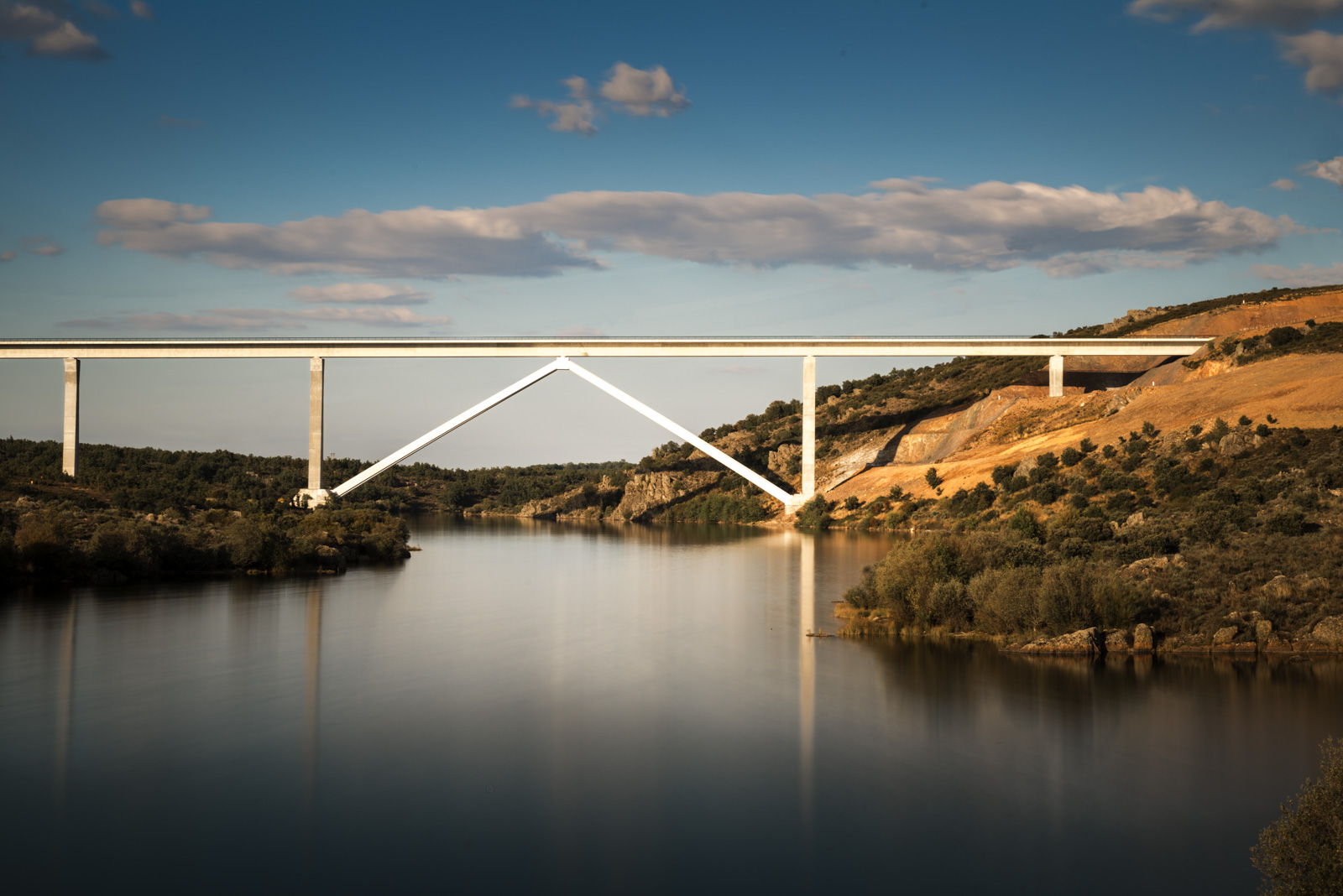
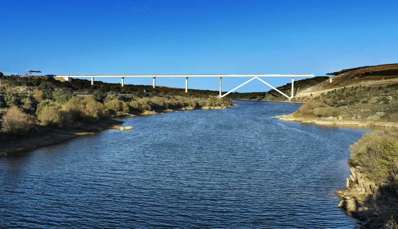
The most remarkable part of the viaduct is the 150 m long span supported on an arch which, due to its virtually straight geometry, appears to be composed of two struts. The solutions we weighed up were the concrete and the steel one.
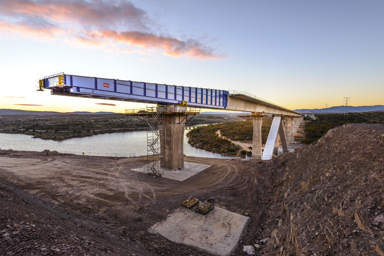
The constructions process of the bridge deck is carried out by incremental launching from Abutment 2. The segments are 25 m long, since the prefabrication yard had the capacity for 3 segments, which correspond to one complete span. The metal launching nose is 45 m long.
The installation of the semi-arches was performed by rotation. The semi-arches were placed vertically on their springers over provisional hinges. Using provisional stay cables anchored in the contiguous pier foundations, the semi-arches were then rotated until meeting at midspan, where they were duly welded together. Subsequently, the springers were blocked against the foundations by embedding the provisional hinges in the concrete.